


M
mA outputs
Added Damping
configuring 76
interaction with density damping 48
interaction with flow damping 27
AO cutoff
configuring 74
interaction with volume flow cutoff 33
configuring 72
Fault Action
configuring 77
options 78
loop testing
using ProLink II 164
using ProLink III 166
using the Field Communicator 167
Lower Range Value and Upper Range Value
configuring 73
default values 74
process variable
configuring 72
options 73
scaling 73
troubleshooting 160, 170, 171
mass flow measurement
configuring 23
cutoff
configuring 27
effect on volume measurement 28
interaction with AO cutoff 28
flow damping 26
measurement units
configuring 23
options 24
meter factor 127
troubleshooting 156
Maximum Pulse Width 82
measurement units
density
configuring 45, 47
options 45
gas standard volume flow rate
configuring 35
options 35
special unit 36
mass flow rate
configuring 23
options 24
special unit 24
pressure
options 56
temperature
configuring 50
options 50
volume flow rate
configuring 29
options 30
special unit 31
menu maps
Field Communicator 220
ProLink II 191
ProLink III 209
Message 67
meter factors, See meter validation
meter validation
alternate method for volume flow 129
definition 115
standard method 127
meter verification, See Smart Meter Verification
Modbus
Additional Communications Response Delay 96
address 96
configuring Modbus/RS-485 digital
communications 96
Floating-Point Byte Order 96
model code 3
P
pickoffs
collecting data 175
troubleshooting 174
polarity
discrete outputs 86
frequency outputs 79
polling
pressure
using ProLink II 51
using the Field Communicator 55
power
power up 7
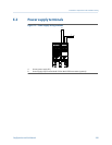
power supply terminals 243
power supply wiring
troubleshooting 163
pressure compensation
configuring
using ProLink II 51
using the Field Communicator 55
overview 51
pressure measurement units
options 56
Index
252 Micro Motion
®
Model 1500 Transmitters with Analog Outputs