


The default setting for Discrete Output Source is Flow Direction.
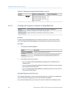
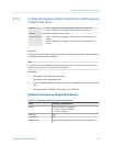
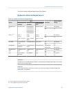
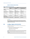
Options for Discrete Output Source
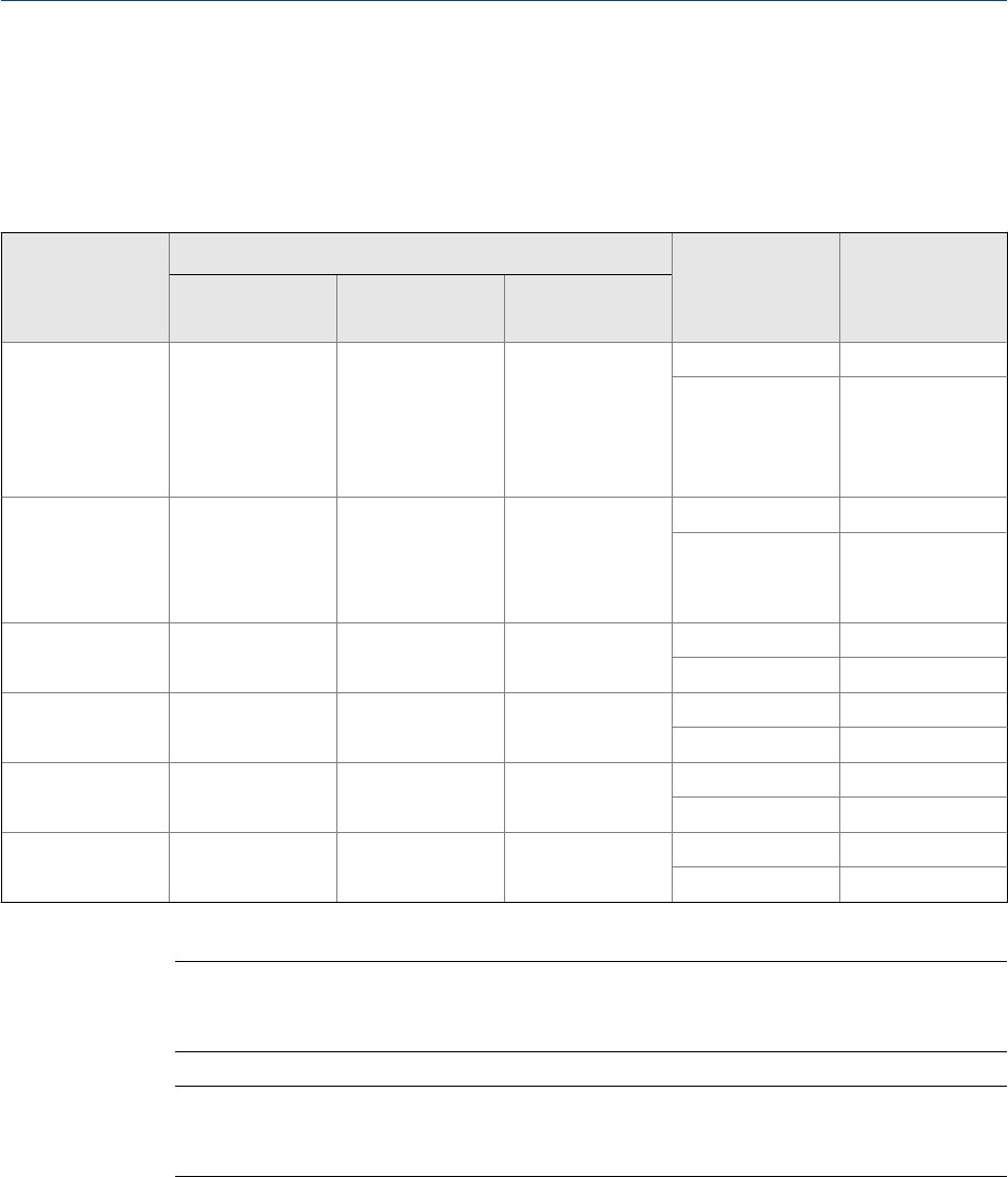
Options for Discrete Output SourceTable 6-8:
Option
Label
Condition
Discrete output
voltage
ProLink II ProLink III
Field Communi-
cator
Discrete Event 1–
5
(1)
Discrete Event x
Enhanced Event 1
Enhanced Event 2
Enhanced Event 3
Enhanced Event 4
Enhanced Event 5
Discrete Event x ON Site-specific
OFF 0 V
Event 1–2
(2)
Event 1
Event 2
Event 1 or Event
2
Event 1
Event 2
Event 1 or Event 2
Status
Event 1
Event 2
Event 1 or Event
2
ON Site-specific
OFF 0 V
Flow Switch
Flow Switch Indi-
cation
Flow Switch Indicator
Flow Switch ON Site-specific
OFF 0 V
Flow Direction
Forward/Reverse
Indication
Forward Reverse In-
dicator
Forward/Reverse Forward flow 0 V
Reverse flow Site-specific
Calibration in Pro-
gress
Calibration in Pro-
gress
Calibration in Pro-
gress
Calibration in Pro-
gress
ON Site-specific
OFF 0 V
Fault
Fault Condition
Indication
Fault Indication
Fault ON Site-specific
OFF 0 V
Important
This table assumes that Discrete Output Polarity is set to Active High. If Discrete Output Polarity is set to Active
Low, reverse the voltage values.
Important
If you assign flow switch to the discrete output, you must also configure Flow Switch Variable, Flow
Switch Setpoint, and Hysteresis.
(1) Events configured using the enhanced event model.
(2)
Events configured using the basic event model.
Integrate the meter with the control system
Configuration and Use Manual 85