


10.3 Flow measurement problems
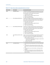
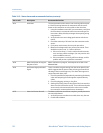
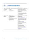
Flow measurement problems and recommended actionsTable 10-3:
Problem Possible causes Recommended actions
Flow indication at no
flow conditions or
zero offset
• Misaligned piping (especially in new in-
stallations)
• Open or leaking valve
• Incorrect sensor zero
• Verify that all of the characterization parame-
ters match the data on the sensor tag.
• If the flow reading is not excessively high, re-
view the live zero. You may need to restore
the factory zero.
• Check for open or leaking valves or seals.
• Check for mounting stress on the sensor
(e.g., sensor being used to support piping,
misaligned piping).
• Contact Micro Motion.
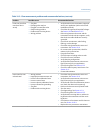
Erratic non-zero flow
rate under no-flow
conditions
• Leaking valve or seal
• Slug flow
• Plugged or coated flow tube
• Incorrect sensor orientation
• Wiring problem
• Vibration in pipeline at rate close to sen-
sor tube frequency
• Damping value too low
• Mounting stress on sensor
• Verify that the sensor orientation is appropri-
ate for your application (refer to the sensor
installation manual).
• Check the drive gain and the pickoff voltage.
See Section 10.26 and Section 10.27.
• If the wiring between the sensor and the
transmitter includes a 9-wire segment, verify
that the 9-wire cable shields are correctly
grounded.
• Check the wiring between the sensor and
transmitter. See Section 10.10.
• For sensors with a junction box, check for
moisture in the junction box.
• Purge the flow tubes.
• Check for open or leaking valves or seals.
• Check for sources of vibration.
• Verify damping configuration.
• Verify that the measurement units are con-
figured correctly for your application.
• Check for slug flow. See Section 10.25.
• Check for radio frequency interference. See
Section 10.13.
• Contact Micro Motion.
Troubleshooting
156 Micro Motion
®
Model 1500 Transmitters with Analog Outputs