


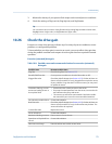
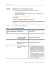
Possible causes and recommended actions for electrical shorts
(continued)
Table 10-11:
Possible cause Recommended action
Liquid or moisture inside the sensor
case
Contact Micro Motion.
Internally shorted feedthrough Contact Micro Motion.
Faulty cable Replace the cable.
Improper wire termination Verify wire terminations inside sensor junction box. The
Micro Motion document titled 9‐Wire Flowmeter Cable Prepa‐
ration and Installation Guide may offer some assistance.
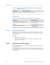
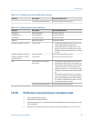
10.28.1 Check the sensor coils
Checking the sensor coils can identify electrical shorts.
Restriction
This procedure applies only to 9-wire remote-mount transmitters and remote transmitters with
remote core processors..
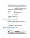
Procedure
1.
Disconnect power to the transmitter.
CAUTION!
If the transmitter is in a hazardous area, wait 5 minutes before continuing.
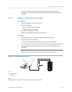
2. Unplug the terminal blocks from the terminal board on the core processor.
3.
Using a digital multimeter (DMM), check the pickoff coils by placing the DMM leads
on the unplugged terminal blocks for each terminal pair. See Table 10‐12 for a list of
the coils. Record the values.
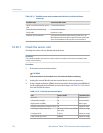
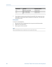
Coils and test terminal pairsTable 10-12:
Coil Sensor model Terminal colors
Drive coil All Brown to red
Left pickoff coil (LPO) All Green to white
Right pickoff coil (RPO) All Blue to gray
Resistance temperature detector (RTD) All Yellow to violet
Lead length compensator (LLC) All except T-Series and CMF400
(see note)
Yellow to orange
Composite RTD T-Series Yellow to orange
Fixed resistor (see note) CMF400 Yellow to orange
Troubleshooting
176 Micro Motion
®
Model 1500 Transmitters with Analog Outputs