


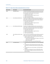
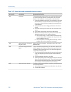

Status alarms and recommended actions (continued)Table 10-2:
Alarm code Description Recommended actions
A008 Density Overrange The sensor is signaling a density reading below 0 g/cm
3
or above
10 g/cm
3
. Common causes for this alarm include partially filled
flow tubes, excessive gas entrainment or flashing, tube fouling
(foreign material stuck in a tube, uneven coating on the inside of
a tube, or a plugged tube), or tube deformation (a permanent
change in tube geometry due to overpressure or hammer ef-
fect).
1.
If other alarms are present, resolve those alarm conditions
first. If the current alarm persists, continue with the recom-
mended actions.
2. Check your process conditions against the values reported
by the flowmeter.
3. Check for air in the flow tubes, tubes not filled, foreign mate-
rial in the tubes, or coating in the tubes.
4. Check for slug flow (two-phase flow).
a. Check for slug flow alarms. If slug flow is the problem,
alarms will be posted.
b. Check the process for cavitation, flashing, or leaks.
c. Monitor the density of your process fluid output under
normal process conditions.
d. Check the values of Slug Low Limit, Slug High Limit, and Slug
Duration.
5. If accompanied by an A003 alarm, check for electrical shorts
between sensor terminals or between the sensor terminals
and the sensor case.
6. Verify that all of the characterization parameters match the
data on the sensor tag.
7. Check the sensor coils (see Section 10.28.1).
8. Check the drive gain and pickoff voltage.
9. Perform a density calibration.
10. Contact Micro Motion.
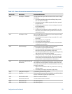
A009 Transmitter Initializing/Warm-
ing Up
The transmitter is in power-up mode. Allow the transmitter to
warm up. The alarm should clear automatically.
If the alarm does not clear:
1.
Check that there is sufficient voltage at the core processor. A
minimum of 11.5 VDC should be available at the core termi-
nals at all times. If there is insufficient power on the core ter-
minals, check that the transmitter is receiving sufficient
power on the power terminals.
2. Make sure the sensor tubes are full of process fluid.
3. Check the wiring between the sensor and the transmitter.
Troubleshooting
Configuration and Use Manual 147