


10.29 Check the core processor LED
The core processor has an LED that indicates different meter conditions.
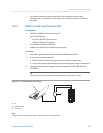
1. Maintain power to the transmitter.
2. Remove the core processor lid. The core processor is intrinsically safe and can be
opened in all environments.
3. Check the state of the core processor LED.
Postrequisites
To return to normal operation, replace the core processor lid.
Important
When reassembling the meter components, be sure to grease all O-rings.
10.29.1 Core processor LED states
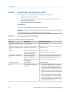
Standard core processor LED statesTable 10-13:
LED state Description Recommended actions
1 flash per second (ON 25%, OFF
75%)
Normal operation No action required.
1 flash per second (ON 75%, OFF
25%)
Slug flow (two-phase flow) See Section 10.25.
Solid ON Zero or calibration in progress No action required.
Core processor receiving be-
tween 11.5 and 5 volts
Check power supply to transmitter.
3 rapid flashes, followed by
pause
Sensor not recognized Check wiring between transmitter and sensor.
Improper configuration Check sensor characterization parameters.
Broken pin between sensor and
core processor
The meter requires factory service.
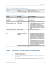
4 flashes per second Fault condition Check alarm status.
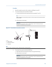
OFF Core processor receiving less
than 5 volts
• Verify power supply wiring to core processor.
• If transmitter status LED is lit, transmitter is re-
ceiving power. Check voltage across terminals
1 (VDC+) and 2 (VDC–) in core processor. If
reading is less than 1 VDC, verify power supply
wiring to core processor. Wires may be switch-
ed.
• If transmitter status LED is not lit, transmitter
is not receiving power. Check power supply. If
power supply is operational, internal transmit-
ter, display, or LED failure is possible – the me-
ter may require factory service.
Troubleshooting
178 Micro Motion
®
Model 1500 Transmitters with Analog Outputs