Configuration and Use Manual 79
Testing and Moving to Production
Operation AppendicesMaintenance and TroubleshootingCommissioning
Note the following:
• During the trim, the transmitter’s mA output will not report process data.
CAUTION! Do not
use the mA output for process control while you are performing the trim.
• Enter the measured value in the same scale that you specified for the mA measurement point.
If you specified “Don’t Know”:
- If you are using ProLink II, enter the measured value in one scale and the tool will display
the equivalent value in the other scale.
- If you are using the Communicator, you must specify the mA measurement point before
you can continue.
• Any trimming performed on the output should not exceed ± 200 microamps. If more trimming
is required, contact Micro Motion customer support.
• If you are using the Communicator, the receiving device value can contain up to two decimal
places.
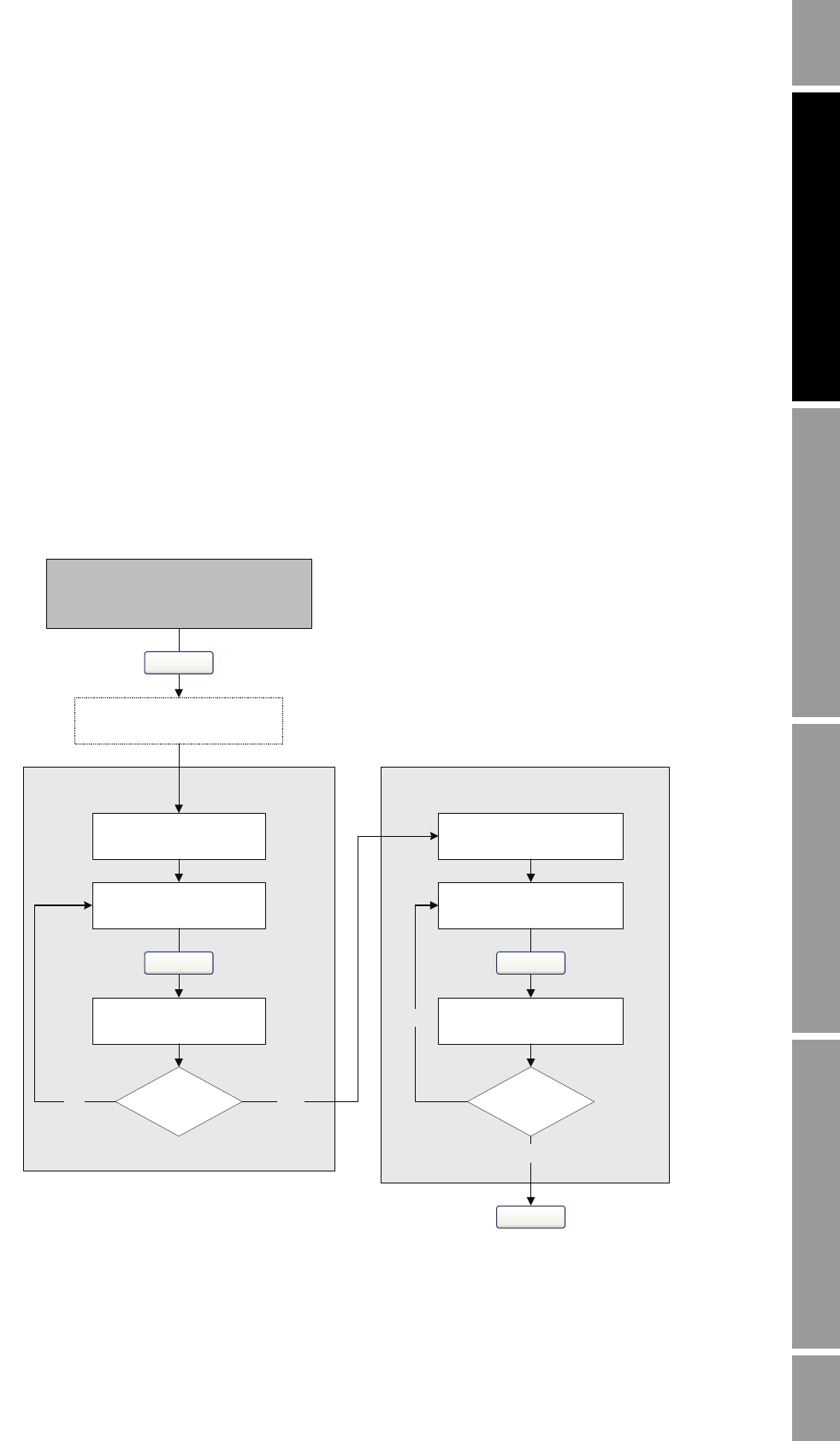
Figure 7-7 Communicator – mA output trim procedure
Read mA output at
receiving device
Read mA output at
receiving device
Equal?
Enter receiving device
value at Communicator
Read mA output at
receiving device
Read mA output at
receiving device
Equal?
Enter receiving device
value at Communicator
4 (12) mA trim 20 mA trim
Yes
No
No
Yes
ENTER
ENTER
OK
OK
On-Line Menu >
3 Diag/Service >
6 Trim Analog Out 1
Set mA measurement point


