


116 Micro Motion
®
Model 2200S Transmitters
Troubleshooting
10.22 Checking the calibration
Improper calibration can cause the transmitter to send unexpected output values. If the transmitter
appears to be operating correctly but sends inaccurate output values, an improper calibration may be
the cause.
Micro Motion calibrates every transmitter at the factory. Therefore, you should suspect improper
calibration only if the transmitter has been calibrated after it was shipped from the factory. Before
performing a calibration, consider meter validation or meter verification and select the appropriate
procedure (see Section 9.2). Contact Micro Motion customer service for assistance.
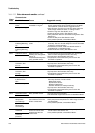
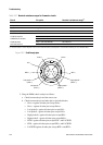
10.23 Checking the test points
Some status alarms that indicate a sensor failure or overrange condition can be caused by problems
other than a failed sensor. You can diagnose sensor failure or overrange status alarms by checking the
flowmeter test points. The test points include left and right pickoff voltages, drive gain, and tube
frequency. These values describe the current operation of the sensor.
10.23.1 Obtaining the test points
You can obtain the test points with a Communicator or ProLink II.
With a Communicator
To obtain the test points with a Communicator:
1. Select
Diag/Service.
2. Select
Test Points.
3. Record the values displayed for
Drive, LPO, RPO, and Tube
With ProLink II
To obtain the test points with ProLink II:
1. Select
Diagnostic Information from the ProLink menu.
2. Record the values displayed for
Tube Frequency, Left Pickoff, Right Pickoff, and Drive
Gain
.
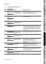
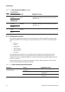
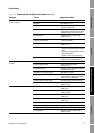
10.23.2 Drive gain problems
Problems with drive gain can appear in several different forms:
• Saturated or excessive (near 100%) drive gain
• Erratic drive gain (e.g., rapid shifting from positive to negative)
• Negative drive gain
See Table 10-5 for a list of possible problems and remedies.