


98 Micro Motion
®
Model 2200S Transmitters
Measurement Performance
9.4 Performing density calibration
Density calibration includes the following calibration points:
• D1 calibration (low-density)
• D2 calibration (high-density)
You must perform both calibrations without interruption, in order.
Note: Before performing the calibration, record your current calibration parameters. If you are using
ProLink II, you can do this by saving the current configuration to a file on the PC. If the calibration
fails, restore the known values.
You can calibrate for density with ProLink II or the Communicator.
9.4.1 Preparing for density calibration
Before beginning density calibration, review the requirements in this section.
Sensor requirements
During density calibration, the sensor must be completely filled with the calibration fluid, and flow
through the sensor must be at the lowest rate allowed by your application. This is usually
accomplished by closing the shutoff valve downstream from the sensor, then filling the sensor with
the appropriate fluid.
Density calibration fluids
D1 and D2 density calibration require a D1 (low-density) fluid and a D2 (high-density) fluid. You
may use air and water.
9.4.2 Density calibration procedures
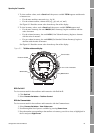
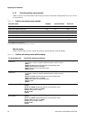
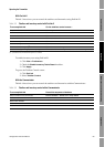
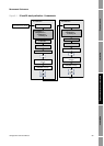
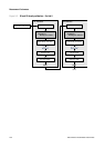
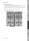
To perform a D1 and D2 density calibration:
• With the Communicator, see Figure 9-1.
• With ProLink II, see Figure 9-2.
Example
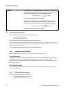
The flowmeter is installed and proved for the first time. The flowmeter
mass measurement is 250.27 lb; the reference device measurement is
250 lb. A mass flow meter factor is determined as follows:
The first mass flow meter factor is 0.9989.
One year later, the flowmeter is proved again. The flowmeter mass
measurement is 250.07 lb; the reference device measurement is
250.25 lb. A new mass flow meter factor is determined as follows:
The new mass flow meter factor is 0.9996.
MeterFactor
MassFlow
1
250
250.27
------------------
× 0.9989==
MeterFactor
MassFlow
0.9989
250.25
250.07
------------------
× 0.9996==