


120 Micro Motion
®
Model 2200S Transmitters
Troubleshooting
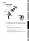
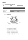
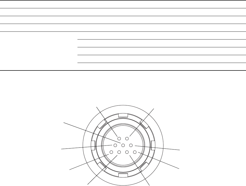
Figure 10-2 Feedthrough pins
5. Using the DMM, check each pin as follows:
a. Check between the pin and the sensor case.
b. Check between the pin and other pins as described below:
• Drive + against all other pins except Drive –
• Drive – against all other pins except Drive +
• Left pickoff + against all other pins except LPO –
• Left pickoff – against all other pins except LPO +
• Right pickoff + against all other pins except RPO –
• Right pickoff – against all other pins except RPO +
• RTD + against all other pins except RTD – and LLC/RTD
• RTD – against all other pins except RTD + and LLC/RTD
• LLC/RTD against all other pins except RTD + and RTD –
Table 10-7 Nominal resistance ranges for flowmeter circuits
Circuit Pin pairs Nominal resistance range
(1)
(1) Actual resistance values depend on the sensor model and date of manufacture. Contact Micro Motion for more detailed data.
Drive Drive + and – 8–1500 Ω
Left pickoff Left pickoff + and – 16–1000 Ω
Right pickoff Right pickoff + and – 16–1000 Ω
Flow tube temperature sensor RTD + and RTD – 100 Ω at 0 °C + 0.38675 Ω / °C
LLC/RTD
• T-Series sensors RTD – and composite RTD 300 Ω at 0 °C + 1.16025 Ω / °C
• CMF400 I.S. sensors RTD – and fixed resistor 39.7–42.2 Ω
• F300 sensors RTD – and fixed resistor 44.3–46.4 Ω
• All other sensors RTD – and LLC 0
Left pickoff +
(LPO +)
Right pickoff +
(RPO +)
Drive + Drive –
Right pickoff –
(RPO –)
Left pickoff –
(LPO –)
LLC
RTD +
RTD –