


106 Micro Motion
®
Model 2200S Transmitters
Troubleshooting
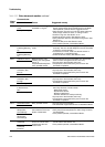
10.10 I/O problems
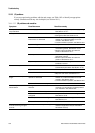
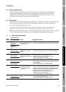
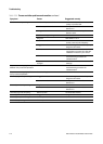
If you are experiencing problems with the mA output, use Table 10-2 to identify an appropriate
remedy. Simulation mode may also be helpful (see Section 10.11).
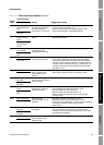
Table 10-2 I/O problems and remedies
Symptom Possible cause Possible remedy
No output
Loop test failed
Power supply problem • Check power supply and power supply wiring.
See Section 10.14.1.
mA output < 4 mA Process condition below LRV • Verify process.
• Change the LRV. See Section 6.2.2.
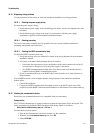
Fault condition if fault action is set to
internal zero or downscale
• Check the fault action settings to verify
whether or not the transmitter is in a fault
condition. See Section 6.2.5.
• If a fault condition is present, see Section 10.8.
Open in wiring • Verify all connections.
Bad mA receiving device • Check the mA receiving device or try another
mA receiving device. See Section 10.16.
• Perform output simulation to locate the
problem. See Section 10.11
.
Bad output circuit • Measure DC voltage across output to verify
that output is active.
• Perform output simulation to locate the
problem. See Section 10.11
.
Output not powered • Check transmitter wiring. See the transmitter
installation manual.
Constant mA output Non-zero HART address • Set HART address to 0 or enable the Loop
Current Mode parameter. See Section 10.19.
Output is fixed in a test mode • Exit output from test mode. See Section 7.3.
Zero calibration failure • Cycle power.
• Stop flow and rezero. See Section 7.2.
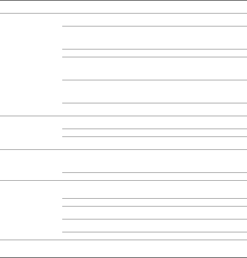
mA output consistently out of
range
Fault condition if fault indicator is set to
upscale or downscale
• Check the fault indicator settings to verify
whether or not the transmitter is in a fault
condition. See Section 6.2.5.
• If a fault condition is present, see Section 10.8.
LRV and URV not set correctly • Check the LRV and URV. See Section 10.20.
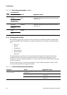
Consistently incorrect mA
measurement
Scaling mismatch between transmitter
and host.
• Ensure that the host is scaled for either 12–20
mA input or 4–20 mA input, as appropriate to
your installation. See Section 8.3.
Output not trimmed correctly • Trim the output. See Section 7.4.
Incorrect flow measurement unit
configured
• Verify flow measurement unit configuration.
See Section 10.20.
Incorrect process variable configured • Verify process variable assigned to mA output.
See Section 6.2.1.
LRV and URV not set correctly • Check the LRV and URV. See Section 10.18.
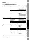
mA reading correct at low
currents but wrong at higher
currents
mA loop resistance may be too high • Verify mA output load resistance is below
maximum supported load (see installation
transmitter manual).