


128 Micro Motion
®
Model 2200S Transmitters
Flowmeter Installation Types and Components
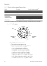
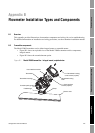
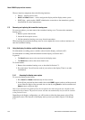
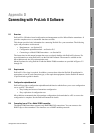
Figure B-2 Model 2200S transmitter – Extended-mount
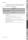
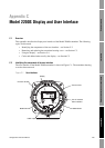
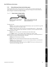
B.3 Terminal diagrams
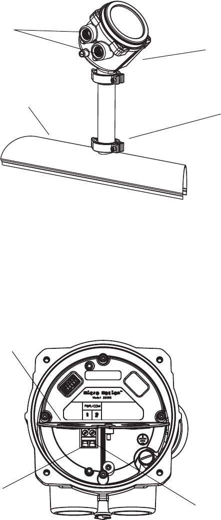
Figure B-3 shows the transmitter’s wiring terminals. These terminals are used for both power supply
and I/O. They are beneath the Warning flap. The transmitter housing cover and the Warning flap
screw must be removed to access the wiring terminals.
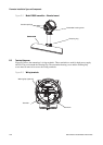
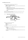
Figure B-3 Wiring terminals
Conduit openings
Clamping ring
Sensor caseSensor case
Transmitter housing cover
Warning flap (opened)
Ter min al 2
Terminal 1