


10 Micro Motion
®
Model 2200S Transmitters
Quick Start
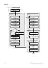
2.4 Menu flowcharts
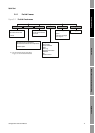
This section provides the following menu flowcharts for the Model 2200S transmitter:
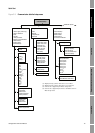
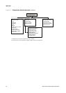
• ProLink II menus
- Main menu – see Figure 2-2
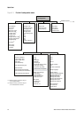
- Configuration menu – see Figures 2-3 and 2-4
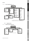
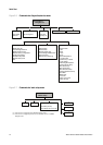
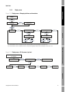
• Communicator menus – see Figures 2-5 through 2-10
• Display menus
- Managing totalizers and inventories – see Figure 2-10
- Off-line maintenance menu: Top level – see Figure 2-11
- Off-line maintenance menu: Version information – see Figure 2-12
- Off-line maintenance menu: Configuration – see Figures 2-13 and 2-14
- Off-line maintenance menu: Simulation (loop testing) – see Figure 2-15
- Off-line maintenance menu: Zero – see Figure 2-16
- Alarm menu – see Figure 2-17
For information on the codes and abbreviations used on the display, see Appendix C.
These menu flowcharts are based on:
• Transmitter software v1.0
• ProLink II v2.8
• Field Communicator device description
Micro Motion 2200S Analog dev rev 1 DD rev 1
Menus may vary slightly for different versions of these components.
Digital communications Fault action
Upscale
Downscale
Internal zero
Not-a-Number
Flow to zero
None
Fault value __________
Fault value __________
Loop current mode
Enabled
Disabled
Burst mode
Enabled
Disabled
Output
Field device variables
PV
PV and % of range
HART vars and PV
current
Field device vars
Var 1 __________
Var 2 __________
Var 3 __________
Var 3 __________
HART variables
(SV, TV, QV)
___ Mass flow
___ Volume flow
___ GSV flow
___ Temperature (process)
___ Density
___ Drive gain
___ Mass total
___ Volume total
___ GSV total
___ Mass inventory
___ Volume inventory
___ GSV inventory
___ Board temperature
___ LPO amplitude
___ RPO amplitude
___ Raw tube frequency
___ Live zero
Configuration Worksheet Transmitter _______________________________