


Configuration and Use Manual 13
Quick Start
Operation AppendicesMaintenance and TroubleshootingCommissioning
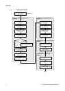
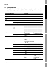
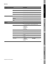
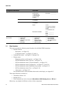
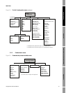
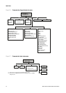
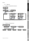
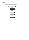
Figure 2-4 ProLink II configuration menu continued
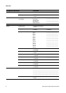
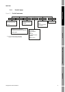
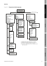
2.4.2 Communicator menus
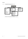
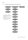
Figure 2-5 Communicator process variables menu
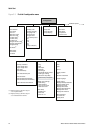
Sensor
· Sensor s/n
· Sensor model num
·Sensor matl
·Liner matl
· Flange
T Series
· FTG
· FFQ
·DTG
·DFQ1
·DFQ2
·K3
·D3
·D4
·K4
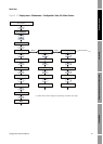
ProLink >
Configuration
Alarm
·Alarm
·Severity
Variable Mapping
· PV is
· SV is
·TV is
·QV is
Special Units
Base mass unit
· Base mass time
· Mass flow conv fact
· Mass flow text
· Mass total text
Base vol unit
(1)
·Base vol time
(1)
· Vol flow conv fact
(1)
· Vol flow text
(1)
· Vol total text
(1)
Base gas vol unit
(2)
· Base gas vol time
(2)
· Gas vol flow conv fact
(2)
· Gas vol flow text
(2)
· Gas vol total text
(2)
Sensor Simulation
Enable simulation mode
Mass flow
·Wave form
· Fixed value
·Period
·Minimum
·Maximum
Density
·Wave form
· Fixed value
·Period
·Minimum
·Maximum
Temperature
·Wave form
· Fixed value
·Period
·Minimum
·Maximum
(1) Displayed only if Vol Flow Type is set to Liquid Volume.
(2) Displayed only if Vol Flow Type is set to Standard Gas Volume.
On-Line Menu >
2 Process variables
View fld dev vars
1 Mass flo
2 Temp
3 Mass totl
4 Dens
5 Mass inventory
6 Vol flo
7 Vol totl
8 Vol inventory
9 Pressure
View output vars
1 View PV-Analog 1
2 View SV
(1)
3 View TV
(1)
4 View QV
(1)
View status Totlizer cntrl
1 Mass totl
2 Vol totl
3 Start totalizer
4 Stop totalizer
5 Reset all totals
6 Reset mass total
7 Reset volume total
2 3 41
(1) Can be used to change the assignment.