


34 Micro Motion
®
Model 2200S Transmitters
Configuring Process Measurement
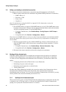
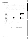
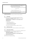
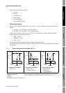
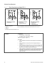
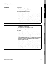
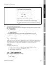
Figure 4-2 Effect of flow direction on mA output: LRV < 0
Example 1
Configuration:
• Flow direction = Forward Only
• mA output: LRV = 0 g/s; URV = 100 g/s
(See the first graph in Figure 4-1.)
As a result:
• Under conditions of zero flow, the mA output of the transmitter is
12 mA.
• Under conditions of reverse flow, the mA output saturates at
11.9 mA.
• Under conditions of forward flow, up to a flow rate of 100 g/s, the
mA output of the transmitter varies between 12 mA and 20 mA in
proportion to (the absolute value of) the flow rate.
• Under conditions of forward flow, if (the absolute value of) the flow
rate equals or exceeds 100 g/s, the mA output will be proportional
to the flow rate up to 20.5 mA, and will be level at 20.5 mA at
higher flow rates.
Reverse
flow
(1)
mA output
20
16
12
–x x0
20
16
–x x0
mA output configuration:
•URV = x
•LRV = –x
• –x < 0
To set the LRV and URV, see Section 6.2.2.
Forward
flow
(2)
Zero flow
Reverse
flow
(1)
Forward
flow
(2)
Zero flow
Flow direction parameter:
• Forward only
Flow direction parameter:
• Reverse only
• Negate/Forward only
20
16
12
–x x0
Reverse
flow
(1)
Forward
flow
(2)
Zero flow
Flow direction parameter:
• Absolute value
• Bidirectional
• Negate/Bidirectional
(1) Process fluid flowing in opposite direction from flow direction arrow on sensor.
(2) Process fluid flowing in same direction as flow direction arrow on sensor.
mA output
mA output
12