


Configuration and Use Manual 61
Operation AppendicesMaintenance and TroubleshootingCommissioning
Chapter 6
Integrating the Meter with the Control System
6.1 Overview
This chapter discusses the following topics and tasks:
• Configuring the mA output – see Section 6.2
• Configuring digital communications – see Section 6.3
Before beginning configuration, make an administrative connection to the transmitter and ensure that
you are complying with all applicable safety requirements.
6.2 Configuring the mA output
The mA output is used to report a process variable. The mA output parameters control how the
process variable is reported.
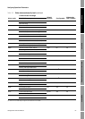
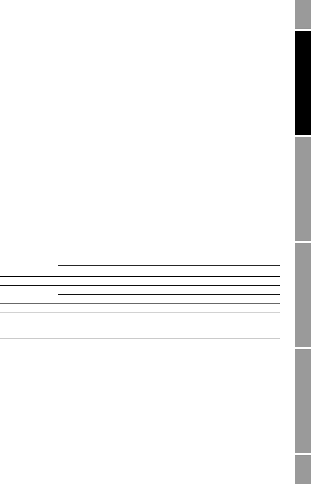
Table 6-1 lists the parameters that must be set for the mA output, and shows the names used for each
parameter by the display, the Communicator, and ProLink II.
Note: If you use the display, you can configure only the process variable, LRV, and URV.
For details on mA output parameters, see Sections 6.2.1 through 6.2.4.
Table 6-1 mA output configuration parameters
Parameter
Parameter name
Display Communicator ProLink II
Process variable SRC PV Primary variable
Range 12 mA PV LRV Lower range value
20 mA PV URV Upper range value
AO cutoff Not accessible PV AO cutoff AO cutoff
Added damping Not accessible PV AO added damp AO added damp
Fault action Not accessible AO1 fault indicator AO fault action
Fault value Not accessible mA1 fault value AO fault level