


130 Micro Motion
®
Model 2200S Transmitters
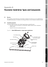
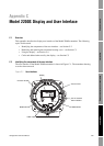
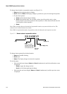
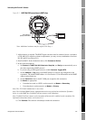
Model 2200S Display and User Interface
The user interface components have the following functions:
• Display – displays process data
•
Scroll and Select buttons – used to navigate the display and the display menu system
• HART clips – used to make a HART administrative connection to the transmitter, typically
from ProLink II or the Communicator
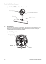
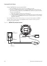
C.3 Removing and replacing the transmitter housing cover
For some procedures, you must remove the transmitter housing cover. To remove the transmitter
housing cover:
1. Remove power from the unit.
2. Loosen the four captive screws.
3. Lift the transmitter housing cover away from the transmitter.
When replacing the transmitter housing cover, be sure to tighten the screws so that no moisture can
enter the transmitter housing.
C.4 Using the display, the buttons, and the display menu system
For information on reading process variables values from the display, see Section 8.5.1.
For information on reading alarm information from the display, see Section 8.6.2.
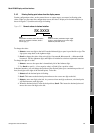
In general:
•The
Scroll button moves to the next item in the display menu.
•The
Select button selects the current item for use.
To use the buttons:
1. Remove the transmitter housing cover, as described in Section C.3.
2. Press the button. You will see the result of your action on the display. There is no other
confirmation.
C.4.1 Accessing the display menu system
To access the display menu system:
1. Press
Scroll and Select simultaneously for four seconds.
2. If the off-line password has been enabled, the word
CODE? appears at the top of the password
screen. Enter the digits of the password one at a time by using
Scroll to choose a number and
Select to move to the next digit.
Note: If you encounter the off-line password screen but do not know the password, wait 60 seconds
without pressing a button. The password screen will time out automatically and you will be returned
to the previous screen.
Depending on the display configuration, you will be taken to either the alarm menu or the off-line
maintenance menu. The structure of the display menu system is provided in Figures 2-10 through
2-17.