


26 Micro Motion
®
Model 2200S Transmitters
Getting Ready to Configure
3.3 Setting up and making an administrative connection
To configure and make the administrative connection using the Communicator or ProLink II:
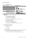
1. Make a startup connection to the transmitter using default HART parameters as listed below:
• HART address = 0
• Baud rate = 1200
• Parity = Odd
• Stop bits = 1
Note: For information on using ProLink II, see Appendix D. For information on using the
Communicator, see Appendix E.
2. Set the HART address as required. Valid HART addresses are 0–63. The HART address must
be unique on the network. You do not need to change the default address unless the transmitter
will be on a multidrop network. To set the HART address:
• Using the Communicator, select
Detailed Setup > Config Outputs > HART Output >
Poll Addr
.
• Using ProLink II, click
ProLink > Configuration > Device.
Note: If you set the HART address to a non-zero value, Loop Current Mode is automatically disabled
and the mA output will not report process data. See Section 6.3.2 for information on enabling Loop
Current Mode.
3. If desired, set the software tag (also called the HART tag). Devices on the network may use
either the HART address or the software tag to communicate with the transmitter. To set the
software tag:
• Using the Communicator, select
Detailed Setup > Device Information > Tag.
• Using ProLink II, click
ProLink > Configuration > Device.
4. Disconnect the startup connection and reconnect using the new parameters.
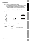
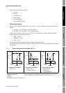
3.4 Working with the mA output scale
If the Micro Motion adapter-barrier is installed, the mA signal received by the host is scaled from
4–20 mA. If the adapter-barrier is not installed, the mA signal received by the host is scaled from
12–20 mA. For the configuration and maintenance tasks listed below, you must know which scale
applies:
• Configuring the fault value (if Fault Action is set to Downscale)
• Performing a loop test on the mA output
• Performing an mA output trim or scaled AO trim
• Viewing output levels
For these tasks, Micro Motion has included scale conversion routines in the Communicator device
description and in ProLink II. These tools will perform scale conversion based on the mA
measurement point (see Section 3.4.1). If you are not using the Communicator or ProLink II, you may
need to perform scale conversion manually (see Section 3.4.2).
3.4.1 Specifying the mA measurement point
The mA measurement point is used by ProLink II and the Communicator to interpret the mA data, that
is, whether to use a 12–20 mA scale or a 4–20 mA scale. Both ProLink II and the Communicator
prompt you to specify this information whenever it is needed.