


14 The Tool Compensation
84
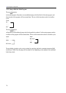
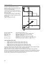
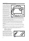
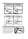
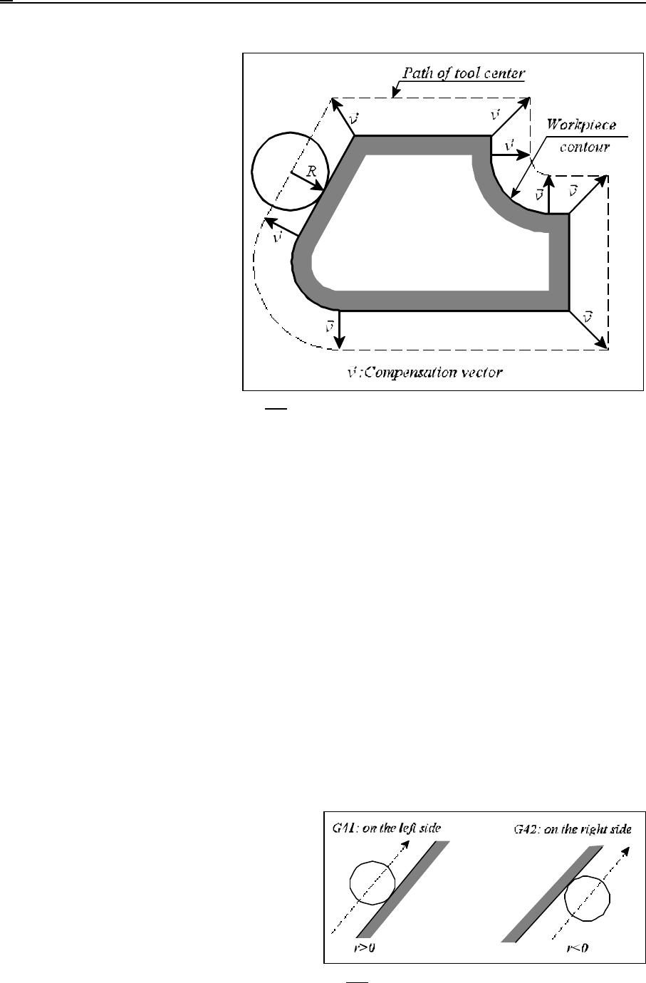
Fig. 14.5-1
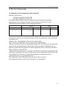
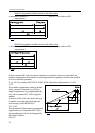
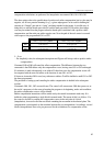
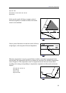
Fig. 14.5-2
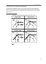
14.5 Cutter Compensation (G38, G39, G40, G41, G42)
To be able to mill the contour of a
two-dimensional workpiece and to
specify the points of that formation
as per the drawing in the program
(regardless of the size of the tool
employed), the control must guide
the tool center parallel to the
programmed contour, spaced by a
tool radius from the latter. The
control will determine the distance
between the path of the tool center
and the programmed contour in
accordance with the compensation
value of the tool radius referred to
by compensation number D.
The compensation vector is a two-
dimensional vector computed over
and over again by the control in each block, modifying the programmed displacements with the
compensation vectors effective at the beginning and end of each block. The length and direction of
each compensation vector obtained vary with the compensation value (called at address D) and the
geometry of the transition between the two blocks.
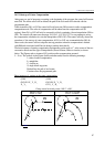
The compensation vectors are computed in the plane selected by instructions G17, G18, G19. This
is the plane of cutter compensation. Movements outside of this plane are not influenced by
compensation. If, e.g., plane X, Y is selected in state G17, the compensation vectors will be
computed in that plane. In this case any movement in Z direction it will be unaffected by the
compensation.
The compensation plane may not be changed while a tool radius compensation is being computed.
Any attempt to do so will result in an error message 3010 PLANE SELECT. IN G41, G42 by the
control.
If a compensation plane is to be defined with additional axes, they have to be defined as parallel
ones in parameters. If, e.g., U is assumed as a parallel axis and the tool radius compensation is to be
applied in plane Z, U, that plane can be selected by the specification of G18 U_Z_.
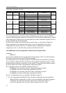
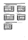
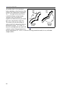
G40: Cutter compensation cancel
G41: Cutter compensation left
G42: Cutter compensation right
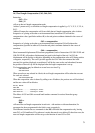
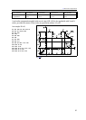
Command G41 or G42 will set up the
compensation computation. In state G41 or
G42 the programmed contours will be tracked
from left side or right side (seen from the travel
direction), respectively. The compensation
number of tool radii has to be specified at
address D. The specification of D00 is always
equivalent to calling zero radius value. The