


4 The Interpolation
30
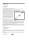
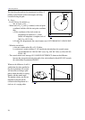
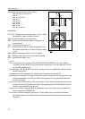
Fig. 4.5-3
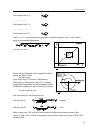
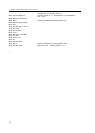
An example of programming a thread-cutting:
N50 G90 G0 X0 Y0 S100 M4
N55 Z2
N60 G33 Z-100 F2
N65 M19
N70 G0 X5
N75 Z2 M0
N80 X0 M4
N85 G4 P2
N90 G33 Z-100 F2
...
Explanation:
N50, N55 - Moving the tool over the center of hole, starting
the spindle in counter-clockwise rotation,
N60 - First thread-cutting cycle, (lead 2mm),
N65 - Oriented spindle stop (the spindle is stopped in a
fixed position),
N70 - Tool retraction along axis X,
N75 - Tool retraction to the top of hole, programmed stop,
the operator adjust the tool to the next thread-cutting
cycle,
N80 - Return to the center of hole, re-start of spindle,
N85 - Waiting for the speed to be assumed by the spindle,
N90 - Second thread-cutting cycle.
L Notes:
– The control returns error message 3020 DATA DEFINITION ERROR G33 if more than two
coordinates are specified at a time in the thread-cutting block, or if both addresses F and E
are specified simultaneously.
– Error message 3022 DIVIDE BY 0 IN G33 is produced when 0 is specified for address E in the
thread-cutting block.
– An encoder has to be mounted on the spindle for the execution of command G33.
– In the course of command G33 being executed, the control will take the feed and spindle override
values automatically to be 100%; the effect of the stop key will only prevail after the block
has been executed.
– On account of the following error of the servo system, overrun and run out allowances have to be
provided for the tool in addition to the part at the beginning and end of the thread in order to
obtain a constant lead all along the part.
– In the course of thread-cutting the feed (in mm/minute) may not exceed the value selected in the
group of parameters FEEDMAX.
– In the course of thread-cutting the speed (r.p.m) of the spindle may not exceed the maximum
speed permissible for the spindle encoder mechanically and electrically (the maximum output
frequency).