


14 The Tool Compensation
104
Fig. 14.5.7-8
Fig. 14.5.7-9
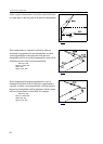
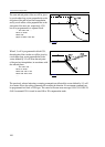
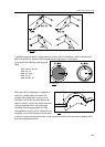
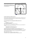
If G28 or G30 is programmed (followed by G29) between two blocks in offset mode, the
compensation vector will be deleted at the end point of the block it positions the tool to the
intermediate point, the tool will move to the reference point, and the vector will be restored at the
end point of the returning block G29.
For example:
...G91 G17
G41...
N110 G1 X80 Y–50
N120 G28 Y80
N130 G29 Y0
N140 X80 Y50
...
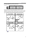
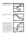
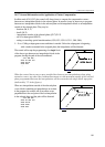
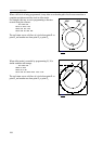
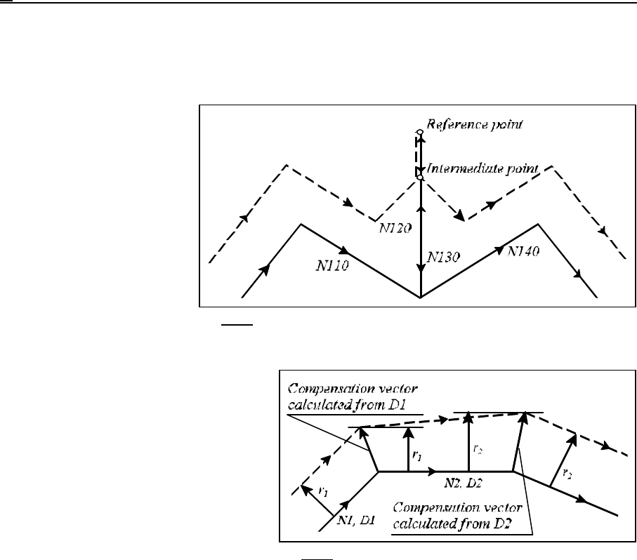
A new compensation value can also be
called at address D in offset mode. In the
event of a reversal in the sign of the
radius, the direction of motion along the
contours will be reversed (see earlier).
Otherwise, the following procedure will
be applicable. The compensation vector
will be calculated with the new radius
value at the end point of the interpolation,
in which the new address D has been
programmed. Since the compensation vector has been computed with the previous radius value at
the start point of that block, the path of the tool center will not be parallel to the programmed path.
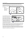
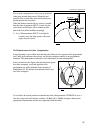
A new radius compensation value can be called at address D in a circular interpolation, too, this
time, however, the tool center will be moving along an arc with a variable radius.
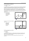
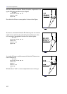
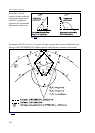
A special instance of the foregoing is canceling or setting up the compensation with D00 or Dnn,
respectively, while in offset mode. Notice the difference in tool paths with reference to the following
example, when the compensation is set up with G41 or G42 and canceled with G40, or when the
compensation is set up and canceled by programming D.