


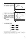

4.7 Cylindrical Interpolation (G7.1)
35
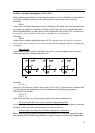
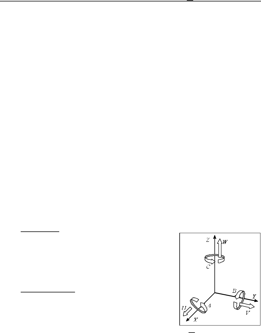
Fig. 4.7-1
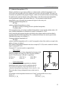
4.7 Cylindrical Interpolation (G7.1)
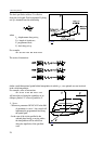
Should a cylindrical cam grooving be milled on a cylinder mantle, cylindrical interpolation is to be
used. In this case the rotation axis of the cylinder and of a rotary axis must coincide. The rotary axis
movements are specified in the program in degrees, which are converted into linear movement along
the mantle by the control in function of the cylinder radius, so that linear and circular interpolation
can be programmed together with another linear axis. The movements resulted after the
interpolations, are re-converted into movement in degrees for the rotary axis.
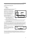
Command cylindrical interpolation on
G7.1 Qr
switches cylindrical interpolation on, where
Q: address of rotary axis taking part in the cylindrical interpolation,
r: cylinder radius.
If for example the rotary axis acting in cylindrical interpolation is axis C and the cylinder radius is 50
mm, cylindrical interpolation is switched on by means of command G7.1 C50.
In the succeeding part program the path to be milled on the cylinder mantle can be described by
specifying linear and circular interpolation. The coordinate for the linear axis must be given in mm,
while that of the rotary axis in degrees (°).
Command cylindrical interpolation off
G7.1 Q0
switches cylindrical interpolation off, i.e. code G corresponds to that of the switch-on, except for the
address of rotary axis being 0.
The cylindrical interpolation indicated in the above example (G7.1 C50) can be switched off with the
help of command G7.1 C0.
Command G7.1 must be issued in a separate block.
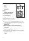
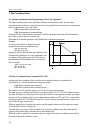
Plane selection
The plane selection code is always determined by the name of the
linear axis parallel to the rotary axis. The rotary axes parallel to
axes X, Y and Z are axes A, B and C, respectively.
G17 X A or
G17 B Y
G18 Z C or
G18 A X
G19 Y B or
G19 C Z
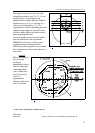
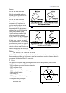
Circular interpolation
It is possible to define circular interpolation in cylindrical
interpolation mode, however only by specifying radius R.
No circular interpolation can be executed in case of
cylindrical interpolation by giving the circle center (I, J, K).
The circle radius is always interpreted in mm or inch, never in
degree.
For example circular interpolation between axes Z and C can be specified in two ways:
G18 Z_ C_
G2 (G3) Z_ C_ R_
G19 C_ Z_
G2 (G3) C_ Z_ R_