


14 The Tool Compensation
111
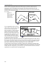
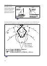
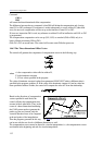
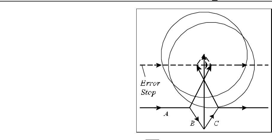
Fig. 14.5.8-8
In the above example an interference error is
returned again because the displacement of the
compensated path in interpolation B is opposite
to the programmed one.
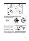
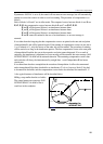
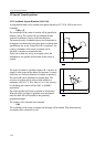
14.6 Three-dimensional Tool Offset (G41, G42)
The 2D tool radius compensation will offset the tool in the plane selected by commands G17, G18,
G19. The application of the three-dimensional tool compensation enables the tool compensation to
be taken into account in three dimensions.
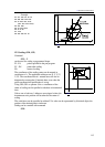
14.6.1 Programming the Three-dimensional Tool Offset (G40, G41, G42)
Command
G41 (G42) X
p
Y
p
Z
p
I J K D (E)
will set up the 3D tool compensation.
X
p
, Y
p
, Z
p
mean axes X, Y, Z or axes parallel to them (if any).
Unless reference is made to an axis the principal axes will be taken into account automatically. For
example,
instruction G41 X I J K refers to space X Y Z
instruction G41 U V Z I J K refers to space U V Z
instruction G41 W I J K refers to space X Y W.
When the three-dimensional tool compensation is set up, each of addresses I, J, K has to be
specified, or else the control will assume the state of 2D tool-radius compensation.
The values specified at addresses I, J, K are the components of the three-dimensional compensation
vector. The values of the components are modal, i.e., each will remain effective until a reference is
made to another value of I, J or K.
The compensation value to be applied can be called at address D.
The dominator constant of compensation calculation can be specified at address E.