


9 Coordinate Systems, Plane Selection
58
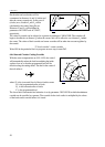
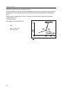
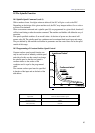
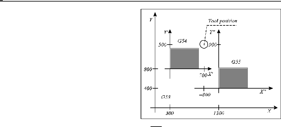
Fig. 9.2.2-2
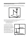
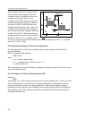
After a change of the work coordinate system,
the tool position will be displayed in the new
coordinate system. For instance, there are two
workpieces on the table. The first work
coordinate system (G54) has been assigned to
zero point of one of the workpieces, which has
an offset of X=300, Y=800 (calculated in the
machine coordinate system). The second work
coordinate system (G55) has been assigned to
the zero point of the other workpiece, which has
an offset of X=1300, Y=400 (calculated in the
machine coordinate system). The tool position is
X'=700, Y'=500 in X', Y's’ coordinate system
(G54). As a result of instruction G55, the tool position will be interpreted in the X", Y" coordinate
system (X"=-300, Y"=900).
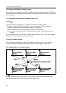
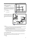
9.2.3 Programmed Setting of the Work Zero Point Offset
It is also programable to set the work coordinate system and the common offset thereof with
program instructions.
This is accomplished with instruction
G10 v L2 Pp
where
p = 0 sets the common offset,
p = 1...6 selecting work coordinate system 1.- 6.
v = offset for each axis.
The coordinate data are entered invariably as rectangular (Cartesian) absolute values. G10 is a one-
shot (non-modal) instruction.
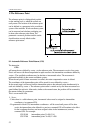
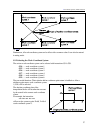
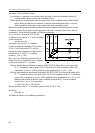
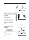
9.2.4 Creating a New Work Coordinate System (G92)
Instruction
G92 v
will establish a new work coordinate system in such a way that coordinate point v of the new system
will be a selected point - e.g. the tool's tip (if a length compensation is programmed) or the base
point of the tool holder (in lack of a length compensation). Afterwards any additional absolute
command will refer to that new work coordinate system, and the positions will also be displayed in
that coordinate system. The coordinates specified in command G92 will always be interpreted as
rectangular absolute values.