


9 Coordinate Systems, Plane Selection
55
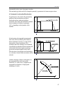
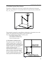
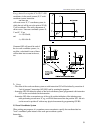
Fig. 9-1
Fig. 9.1-1
9 Coordinate Systems, Plane Selection
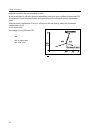
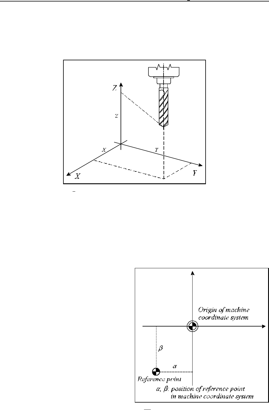
The position, to which the tool is to be moved, is specified with coordinate data in the program.
When 3 axes are available (X, Y, Z), the position of the tool is expressed by three coordinate data
X____ Y____ Z____ :
The tool position is expressed by as many different coordinate data as is the number of axes on the
machine. The coordinate data refer invariably to a given coordinate system.
The control will differentiate three different coordinate systems.
1. the machine coordinate system,
2. the workpiece's coordinate system,
3. the local coordinate system.
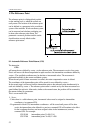
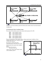
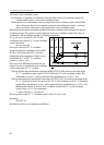
9.1 The Machine Coordinate System
The machine zero point, i.e., the origin of the
machine coordinate system, is a point on the
given machine-tool, that is usually defined by the
machine tool builder. The control will define the
machine coordinate system at the time of
returning to the reference point.
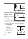
Once the machine coordinate system has been
defined, it will not be altered by the change of
the work coordinate system (G54 ... G59) or
by other coordinate transformation (G52, G92),
only by a power-off of the control system.