


2 Controlled Axes
17
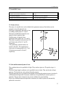
Fig. 2.1-1
2 Controlled Axes
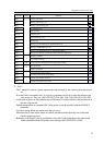
Number of Axes (in basic configuration) 3 axes
In expanded configuration 5 additional axes (8 axes altogether)
Number of axes to be moved simultaneously 8 axes (with linear interpolation)
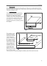
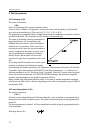
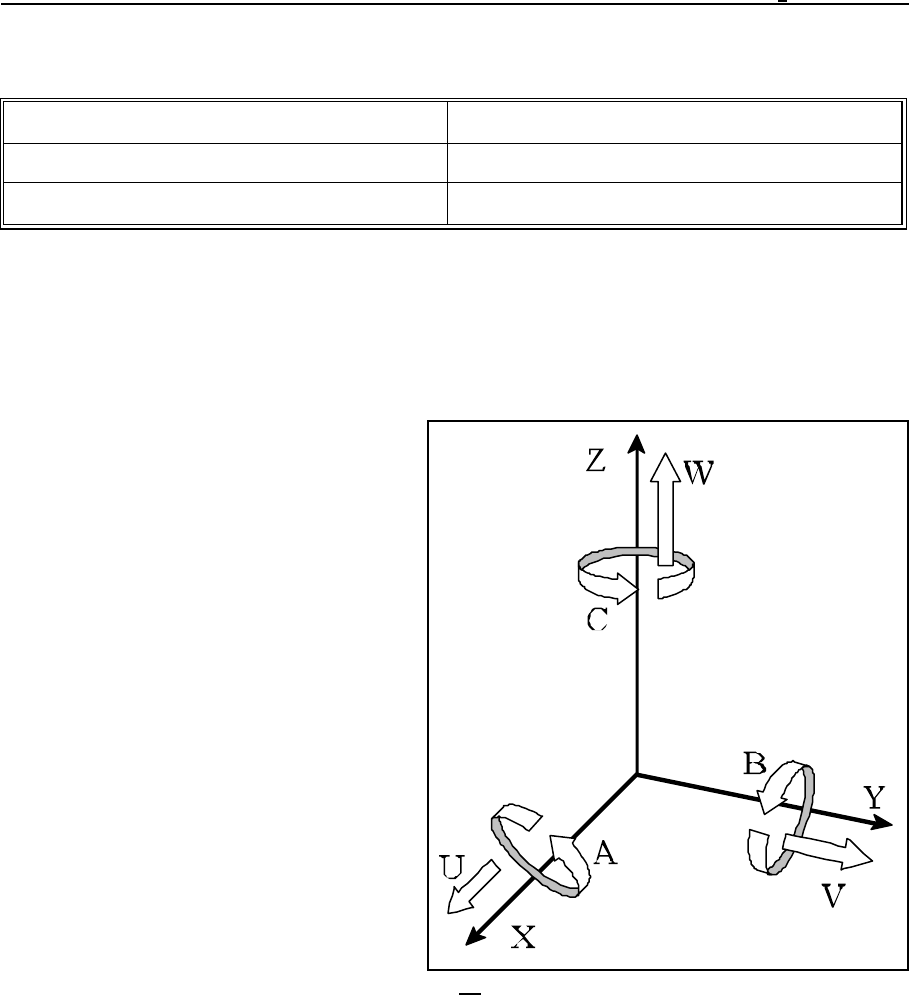
2.1 Names of axes
The names of controlled axes can be defined in the parameter memory. Each address can be
assigned to one of the physical axes.
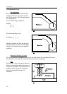
In the basic configuration, the names of axes
in a milling control system: X, Y and Z.
The names of additional (expansion) axes
depend on their respective types.
Possible names of expansion axes
performing linear motions are: U,V and W.
When they are parallel to the main axes X,Y
and Z, their name will be U,V and W,
respectively.
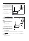
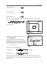
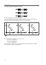
Axes performing rotational motions are
termed A, B and C. The rotational axes
whose axle of rotation parallel to X, Y and
Z directions are termed A, B and C,
respectively.
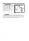
2.2 Unit and Increment System of Axes
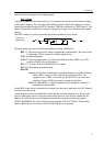
The coordinate data can be specified in 8 digits. They can have signs, too. The positive sign + is
omitted.
The data of input length coordinates can be specified in mm or inches. They are the units of input
measures. The desired one can be selected from the program.
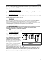
The path-measuring device provided on the machine can measure the position in mm or in inches. It
will determine the output unit of measures, which has to be specified by the control system as a
parameter. The two units of measures may not be combined on a given machine.
In the case of different input and output units of measures, the control system will automatically
perform the conversion.