


14 The Tool Compensation
102
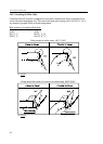
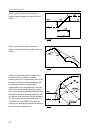
Fig. 14.5.7-3
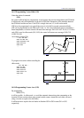
Fig. 14.5.7-4
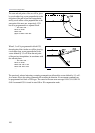
Fig. 14.5.7-5
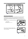
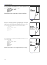
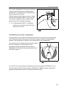
If no cut is feasible in direction Z unless the radius compensation is set
up, the following procedure may be adopted:
...G17 G91...
N110 G41 G0 X50 Y70 D1
N120 G1 Z-40
N130 Y40
...
Now the tool will have a correct path as is shown in the Figure.
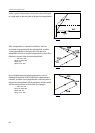
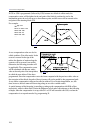
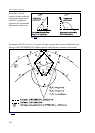
If, however, movement in direction Z is broken up into two sections
(rapid traverse and feed), the path will be distorted because of the
two consecutive interpolations outside of the selected plane:
...G17 G91...
N110 G41 G0 X50 Y70 D1
N120 Z-35
N130 G1 Z-5
N140 Y40
...
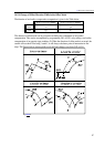
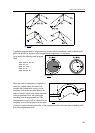
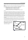
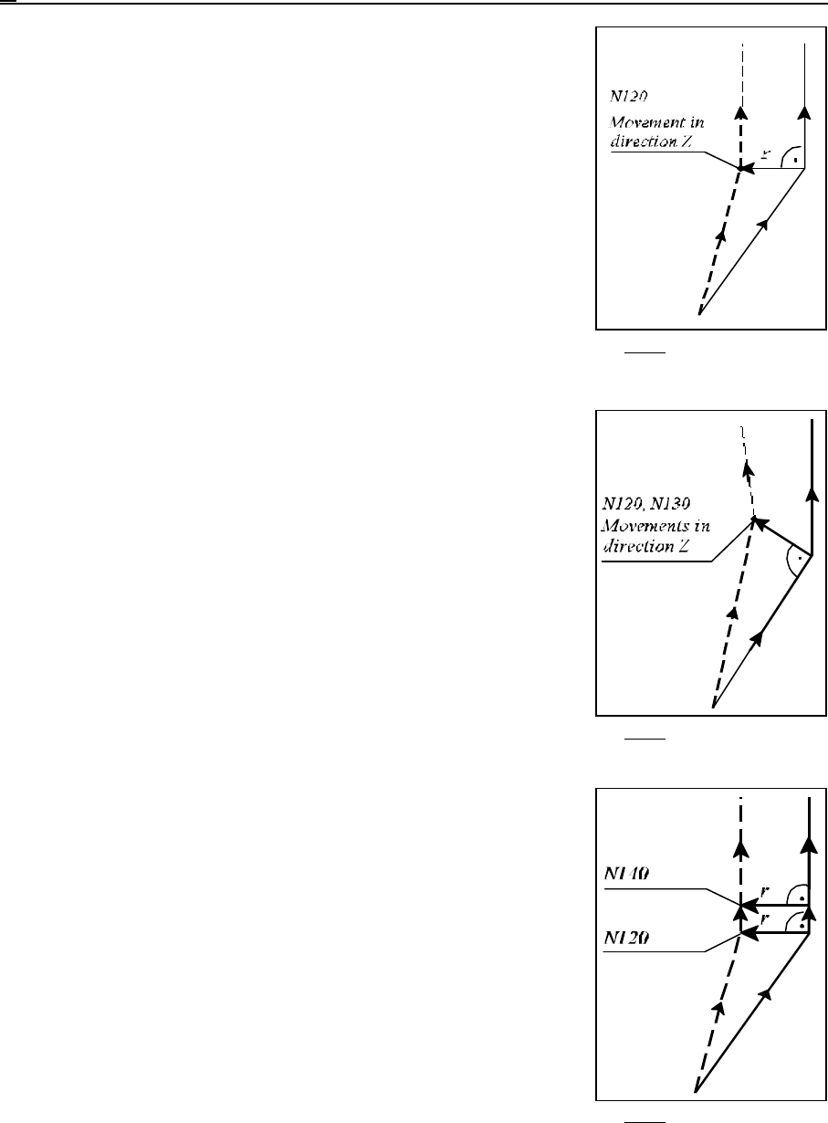
As a trade-off, insert a small movement in direction Y between two
ones in direction Z:
...G17 G91...
N110 G41 G0 X50 Y69 D1
N120 Z-35
N130 Y1
N140 G1 Z-5
N150 Y40
...
With the above "trick" a correct compensation vector can be got.