


9 Coordinate Systems, Plane Selection
59
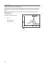
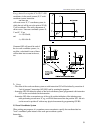
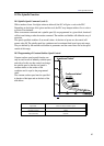
Fig. 9.2.4-1
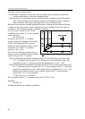
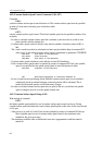
Fig. 9.2.4-2
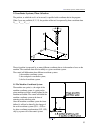
If, e.g., the tool is at a point of X=150, Y=100
coordinates, in the actual (current) X, Y work
coordinate system, instruction
G92 X90 Y60
will create a new X', Y' coordinate system, in
which the tool will be set to the point of X'=90,
Y'=60 coordinates. The axial components of
offset vector v' between coordinate systems X,
Y and X', Y' are
v'
x
=150-90=60,
and
v'
y
=100–60=40.
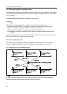
Command G92 will prevail in each of
the six work coordinate systems, i.e.,
an offset v calculated for one of them
will be taken into account in the rest,
too.
L Notes:
– The offset of the work coordinate system set with instruction G92 will be deleted by execution of
"end of program" instructions (M2, M30) and by resetting the program.
– Instruction G92 will delete the offsets of the local coordinate system (programmed with instruction
G52) on the axes included in the instruction.
– Instruction G92 offers a convenient way of the cyclic position indication of the indexing rotary
table performing several turns. If, e.g., axis B has been turned into the position 360°, the axis
can be moved to position 0° without any physical movement by programming G92 B0.
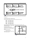
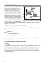
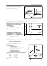
9.3 Local Coordinate System
When writing part programs, it is sometimes more convenient to specify the coordinate data in a
"local" coordinate system instead of the work part coordinate system.
Instruction
G52 v