


15 Special Transformations
116
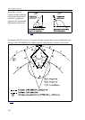
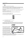
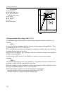
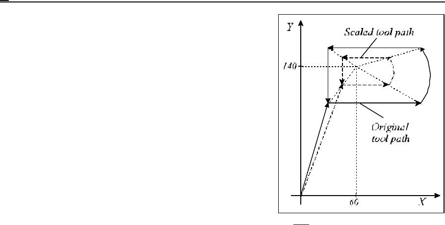
Fig. 15.2-2
For example:
N1 G90 G0 X0 Y0
N2 G51 X60 Y140 P0.5
N3 G1 X30 Y100 F150
(G91 X30 Y100 F150)
N4 G91 X100
N5 G3 Y60 R100
N6 G1 X-100
N7 Y-60
N8 G50 G90 X0 Y0
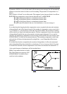
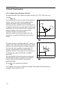
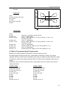
15.3 Programmable Mirror Image (G50.1, G51.1)
A programmed shape can be projected as a mirror image along the coordinates selected in v by
command
G51.1 v
in such a way that the coordinates of the axis (or axes) of mirror image can be specified in v. The v
coordinate may be X, Y, Z, U, V, W, A, B, C.
The v coordinate data entered here are interpreted as rectangular coordinate data even when polar
coordinate data specifications are set up.
Using G90, G91 or operator I, the v coordinates of the axes of the mirror image can be specified as
absolute or incremental data.
No mirror image will be on the axis, for the address of which no value has been assigned.
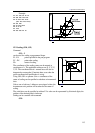
Command
G50.1 v
will cancel the mirror image on axis (axes) specified at v. Any arbitrary data can be written for the v
coordinates, its effect will only record the fact of canceling.
When this command is issued, no rotation or scaling command may be in effect. Otherwise an error
message 3000 MIRROR IMAGE IN G51, G68 is returned.
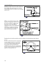
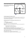
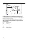
When a mirror image is applied on an axis of composing the selected plane:
– the circle direction is reversed automatically (interchange of G02, G03)
– the angle of rotation is assigned an opposite meaning (G68).