


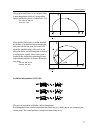
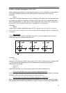
4.6 Polar Coordinate Interpolation (G12.1, G13.1)
31
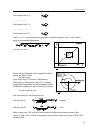
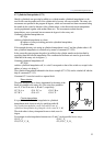
Fig. 4.6-1
4.6 Polar Coordinate Interpolation (G12.1, G13.1)
Polar coordinate interpolation is a control operation method, in case of which the work described in
a Cartesian coordinate system moves its contour path by moving a linear and a rotary axis.
Command
G12.1
switches polar coordinate interpolation mode on. The path of the milling tool can be described in the
succeeding part program in a Cartesian coordinate system in the usual way by programming linear
and circular interpolation, by taking the tool radius compensation into account. The command must
be issued in a separate block and no other command can be written beside.
Command
G13.1
switches polar coordinate interpolation mode off. The command must be issued in a separate
block and no other command can be written beside. It always registers state G13.1 after power-
on or reset.
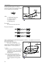
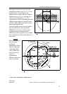
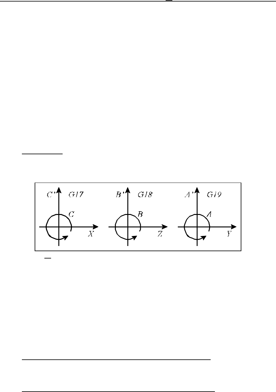
Plane selection
A plane determining the address of the linear and the rotary axis to be applied must be selected
before switching polar coordinate interpolation on.
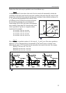
Command
G17 X_ C_
selects axis X for linear axis, while as for the rotary axis it is axis C. The virtual axis is indicated with
C’ on the diagram, the programming of which is implemented by defining length measures.
With the help of commands
G18 Z_ B_
G19 Y_ A_
further linear and rotary axes can be selected together in the above mentioned way.
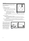
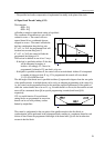
Work zero point offset in the course of polar coordinate interpolation
In case of using polar coordinate interpolation the origin of the applied work coordinate system must
be chosen so that it coincides with the rotation axis of the circular axis.
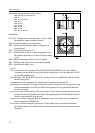
Position of the axes when polar coordinate interpolation is switched on
Before switching polar coordinate interpolation on (command G12.1) make sure that the circular
axis position is 0. The linear axis position can either be negative or positive but it cannot be 0.