


10 The Spindle Function
65
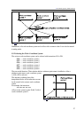
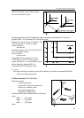
10.2.3 Selecting an Axis for Constant Surface Speed Control
The axis, which position the constant surface speed is calculated from, is selected by parameter
1182 AXIS. The logic axis number must be written at the parameter.
If other than the selected axis is to be used, the axis from which the constant surface speed is to be
calculated can be specified by means of command
G96 P.
Interpretation of address P:
P1: X, P2: Y, P3: Z,
P4: U, P5: V, P6: W,
P7: A, P8: B, P9: C
– The value set at address P is modal. After power on the control activates constant surface speed
control to the axis set at parameter AXIS.
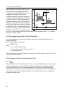
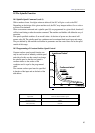
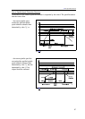
10.3 Spindle Position Feedback
In normal machining the NC will issue a speed command to the power amplifier of the spindle,
proportional to the programmed speed (value specified at address S). Now this amplifier will be
working in speed-control mode.
Some technological tasks may, however, require the spindle to be brought to a particular angular
position. This is referred to as spindle positioning or indexing.
Prior to positioning, the NC will set the power amplifier of the spindle to position-controlled mode.
In practice this means that the NC will not issue a speed command proportional to code S any
more, instead, it will measure the position of the spindle by the use of an encoder mounted on the
spindle, and will issue a command to the servo amplifier in accordance with the desired angular
displacement (similar to the rest of controlled axes). This is the position feedback.
To be able to position the spindle on a particular machine, an encoder has to be mounted on the
spindle and the power amplifier of the spindle must be capable of operation in position feedback
mode as well.
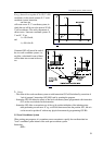
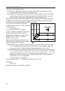
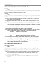
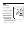
10.4 Oriented Spindle Stop
The "spindle orientation" or the "oriented spindle stop" refers to the function of stopping the spindle
in a particular angular position. This may be necessary, e.g., for an automatic tool change or for the
execution of some drilling cycles. The possibility of orientation on a particular machine must be
specified by parameter ORIENT1 in parameters. The command of spindle orientation is issued by
function M19, but it may also be produced by some other function depending on the particular
machine-tool. The orientation may be carried out in one of two different ways.
If the spindle cannot be used in position control mode, the orientation is feasible by turning the
spindle to a proximity switch mounted on the machine.
If the spindle can be used in position control mode, command M19 will cause the control to return
to the zero pulse of the spindle encoder. The control will automatically close the position control
loop.