


16 Automatic Geometric Calculations
130
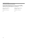
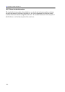
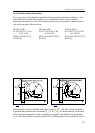
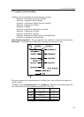
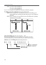
Fig. 16.3.3-3 Fig. 16.3.3-4
Let us see an example:
%O9983
N10 G17 G0 X90 Y0 M3 S200
N20 G42 G1 X50 D0
N30 G3 X-50 Y0 R50
N40 G1 X-50 Y42.857 ,A171.87 Q-1
N50 G40 G0 Y70
N60 X90
N70 M30
%
%O9984
N10 G17 G0 X90 Y0 M3 S200
N20 G42 G1 X50 D0
N30 G3 X-50 Y0 R50
N40 G1 X-50 Y42.857 ,A171.87 Q1
N50 G40 G0 Y70
N60 X90
N70 M30
%
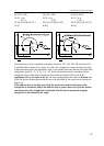
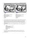
Linear block N40 is defined over because both the end point coordinates (X–50 Y42.875) and the
angle (,A171.87) of the straight line are specified. Therefore X–50 Y0 coordinates of the circle
programmed in the previous block N30 are not referred to as end point coordinates, but only as a
point which is intersected by the circle and the end point is the calculated intersection. In program
No. O9983 the nearer intersection in the direction of the straight line is given (Q–1), while in O9984
the farther one is specified (Q1).
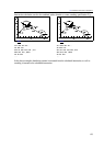
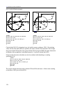
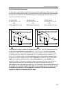
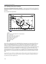
Circular-linear intersection calculation can also be combined with a chamfer or rounding
specification. E.g.:
%O9983
N10 G17 G0 X90 Y0 M3 S200
N20 G42 G1 X50 D0
N30 G3 X-50 Y0 R50 ,R15
N40 G1 X-50 Y42.857 ,A171.87 Q-1
N50 G40 G0 Y70
N60 X90
N70 M30
%
In the example a 15mm-rounding is programmed in block N30 (,R15). The control calculates the
intersection of blocks N30 and N40 and inserts the programmed rounding to the resulting contour.