


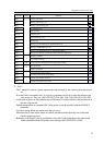
4 The Interpolation
25
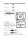
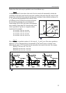
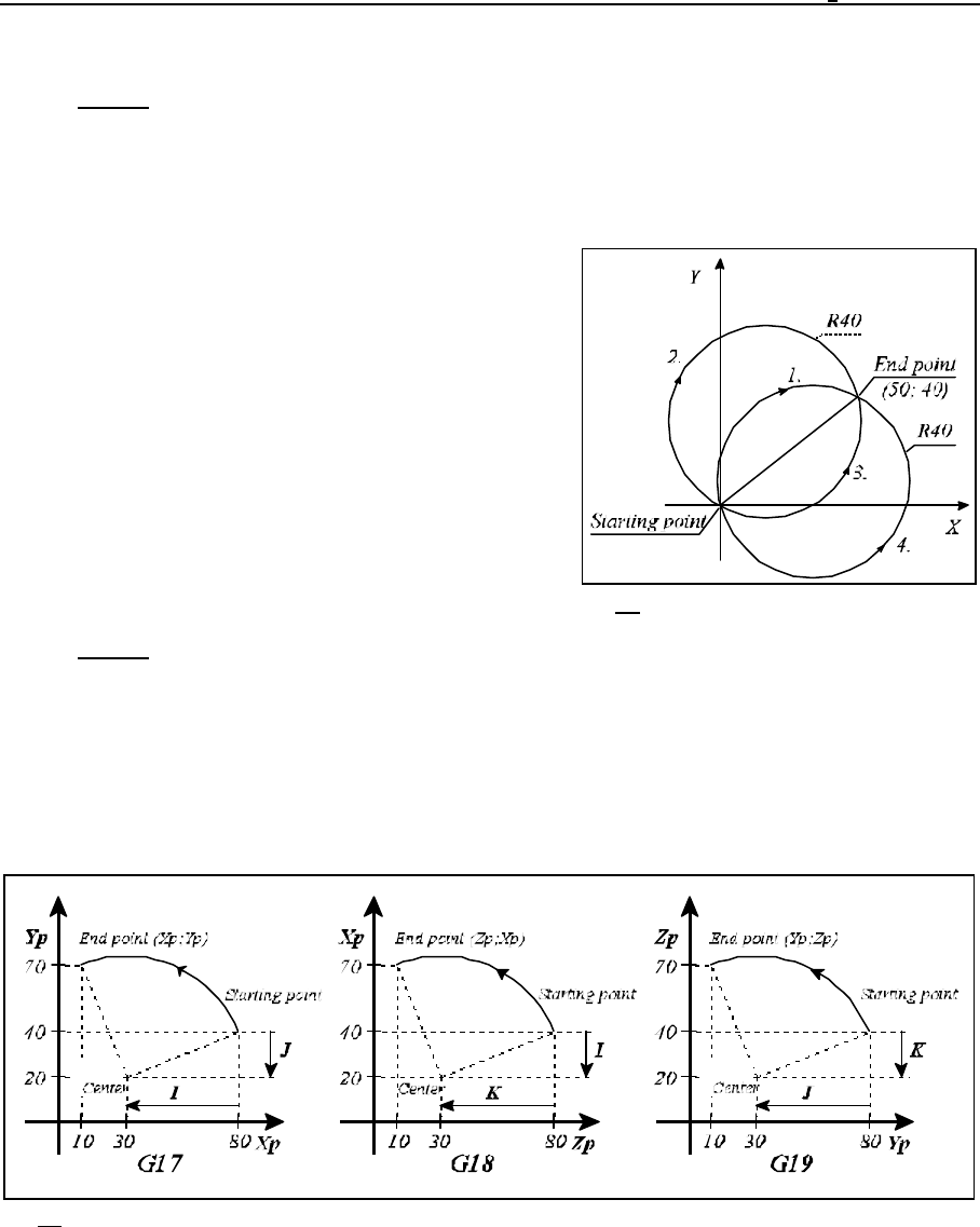
Fig. 4.3-2
Fig. 4.3-3
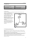
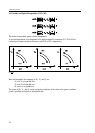
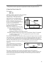
Further data of the circle may be specified in one of two different ways.
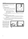
Case 1
At address R where R is the radius of the circle. Now the control will automatically calculate the
coordinates of the circle center from the start point coordinates (the point where the control is in the
instant of the circle block being entered), the end point coordinates (values defined at addresses X
p
,
Y
p
, Z
p
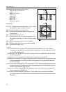
) and from the programmed circle radius R. Since
two different circles of radius R can be drawn between
the start and the end points for a given direction of
circumventing (G02 or G03), the control will interpolate
an arc smaller or larger than 180° when the radius of the
circle is specified as a positive or a negative number,
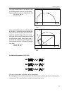
respectively. For example:
Arc section 1: G02 X50 Y40 R40
Arc section 2: G02 X50 Y40 R-40
Arc section 3: G03 X50 Y40 R40
Arc section 4: G03 X50 Y40 R-40
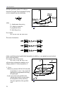
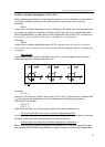
Case 2
The circle center is specified at address I, J, K for the X
p
, Y
p
and Z
p
axes. The values specified at
addresses I, J, K are interpreted always incrementally by the control system, so that the vector
defined by the values of I, J, K points from the start point to the center of the circle. For example:
With G17: G03 X10 Y70 I-50 J-20
With G18: G03 X70 Z10 I-20 K-50
With G19: G03 Y10 Z70 J-50 K-20