


8 The Reference Point
52
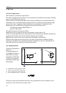
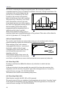
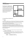
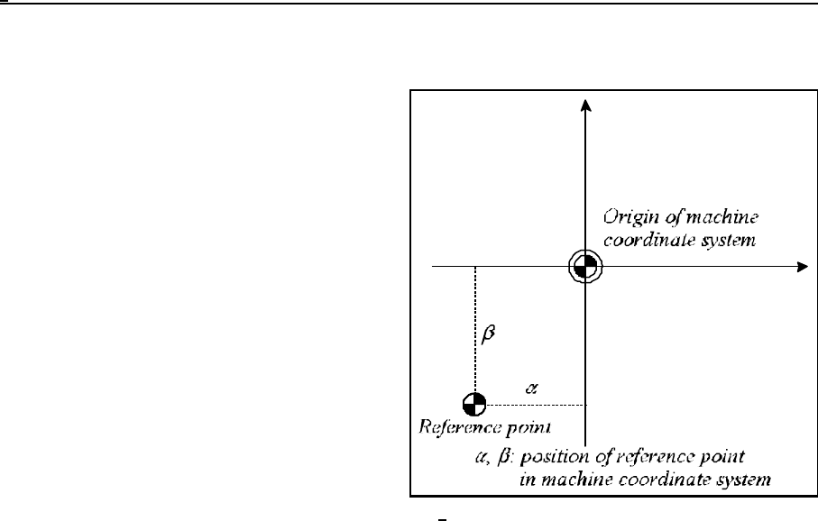
Fig. 8-1
8 The Reference Point
The reference point is a distinguished position
on the machine-tool, to which the control can
easily return. The location of the reference point
can be defined as a parameter in the coordinate
system of the machine. Work coordinate system
can be measured and absolute positioning can
be done after reference point return. The
parametric overtravel positions and the stroke
check function are only effective after
reference-point return.
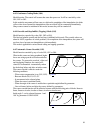
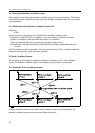
8.1 Automatic Reference Point Return (G28)
The instruction
G28 v
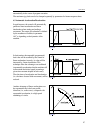
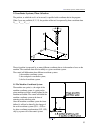
will return the axes defined by vector v to the reference point. The movements consist of two parts.
First it will move with linear interpolation in rapid traverse to the intermediate coordinates defined by
vector v. The specified coordinates may be absolute or incremental values. The movement is
performed invariably in the current coordinate system .
When the end point of linear movement is reached, the cutter compensation vector is deleted.
The coordinates of the intermediate point will be stored for axes defined by vector v.
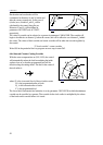
In the second stage it will move from the intermediate point to the reference-point simultaneously in
each axis defined by vector v. The reference-point return is carried out by non-linear movement at a
speed defined for each axis. Afterwards, similar to the manual return, the position will be assumed in
the manner defined by parameters.
This is a non-modal code.
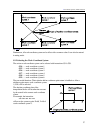
L Notes:
– Unless there is a valid reference point, incremental values must be assigned to intermediate
coordinates v in command G28.
– Programmed in block G28, intermediate coordinates v will be stored until power-off. In other
words, the intermediate value defined in a previous command G28 will continue to be effect
for the coordinates that have not been assigned values in the instantaneous (current)
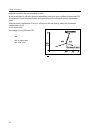
command G28. For example:
G28 X100 intermediate point: X=100, Y=0
G28 Y200 intermediate point: X=100, Y=200