


8 The Reference Point
53
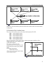
8.2 Automatic return to reference points 2nd, 3rd, 4th (G30)
Series of instructions
G30 v P
will send the axes of coordinates defined at the addresses of vector v to the reference point defined
at address P.
P1=reference point 1
P2=reference point 2
P3=reference point 3
P4=reference point 4
The reference points are special positions defined by parameters (REFPOS1, ..., REFPOS4) in the
coordinate system of the machine-tool, used for change positions, e.g., positions of tool change or
palette change. The first reference point is invariably the position of the machine's reference point,
i.e., the point to which the control moves when returning to the reference point.
The instruction is only applicable after the machine's reference point has been returned.
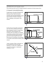
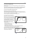
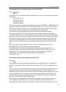
The movement consists of two parts. First it will move by a linear motion to the intermediate
coordinates defined by vector v, with rapid traverse. The specified coordinates may be absolute or
incremental values. The movement is carried out invariably in the current coordinate system. When
the end point of linear movement is reached, the cutter compensation vector will be deleted. The
coordinates of the intermediate point will be stored in the current coordinate system for the axes
defined by vector v. Stored in this way, the coordinates will overwrite those stored in instruction
G28.
In the second phase, the axes defined by vector v will move with rapid traverse from the
intermediate point to the reference point selected at address P.
The reference point is returned by disregarding the compensation vectors (length, offset, 3
dimensional offsets) they need not be deleted before instruction G30 is issued but they will be
implemented by the control when further movements are being programmed. The cutter
compensation is re-established automatically in the first movement block.
A non-modal code.
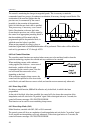
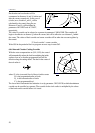
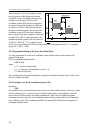
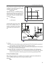
8.3 Automatic Return from the Reference Point (G29)
Instruction
G29 v
will return the control from the reference point along the axes defined in vector v. Following G28
and G30, command G29 will be executed in the same manner. The return is accomplished in two
stages.
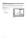
In the first stage it will move from the reference point to the intermediate point recorded during the
execution of instruction G28 or G30, in the axes defined by vector v. The coordinates of the
intermediate point are modal, in other words, the control will take the previous values into account if
reference is made to an axis, to which no coordinate has been transferred in block G28 or G30
preceding G29. It will move to the intermediate point by taking into account the tool length, tool
offset and 3-dimensional tool radius compensations.
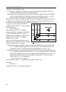
The coordinates of the intermediary point are effective invariably in the coordinate system of the
current workpiece. Accordingly if, e.g., a change of workpiece coordinate system has been
programmed after reference point return and before instruction G29, the intermediate point will be