


14 The Tool Compensation
101
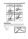
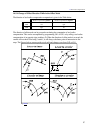
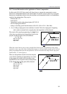
Fig. 14.5.7-1
Fig. 14.5.7-2
14.5.7 General Information on the Application of Cutter Compensation
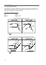
In offset mode (G41, G42), the control will always have to compute the compensation vectors
between two interpolation blocks in the selected plane. In practice it may be necessary to program
between two interpolation blocks in the selected plane a non-interpolation block or an interpolation
outside of the selected plane. They may be
– functions (M, S, T)
– dwell (G4 P)
– interpolation outside of the selected plane ([G17] G1 Z)
– call of a subprogram (M98 P)
– setting or canceling special transformations (G50, G51, G50.1, G51.1, G68, G69).
L Note: Calling a subprogram some carefulness is needed. Unless the subprogram is beginning
with a motion command in the assigned plane, the interpolation will be distorted.
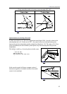
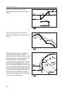
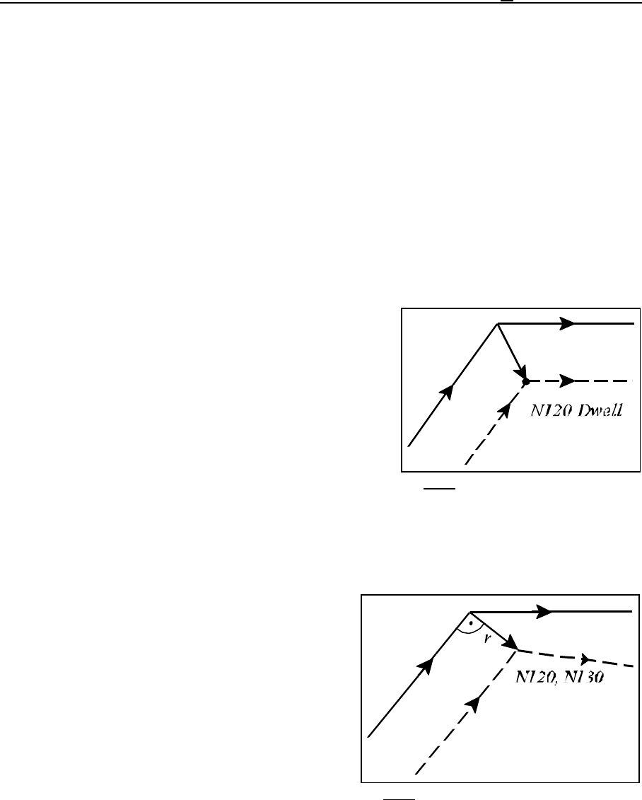
The control will accept the programming of a single block
of the above type between two interpolation blocks in the
program, leaving the path of the tool unaffected:
...G17 G42 G91...
N110 G1 X50 Y70
N120 G4 P2
N130 X60
...
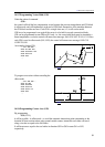
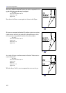
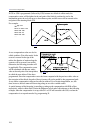
When the control inserts one or more straight lines between two interpolations when going
around a corner, any other block without movement or with movement outside of the selected
plane programmed between the interpolations will be executed at the single block stop point
(indicated by "S" in the figures).
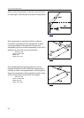
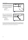
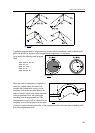
When two interpolations outside of the selected plane
or two blocks containing no interpolations are written
in the program, the control will set an offset vector
perpendicular to the end point of the last interpolation
in the selected plane and the path will be distorted:
...G17 G42 G91...
N110 G1 X50 Y70
N120 G4 P2
N130 S400
N140 X60
...