


14 The Tool Compensation
78
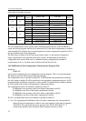
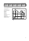
Limit values of geometry and wear:
input units output units
increment
system
geometry value wear value
unit of
measure
mm mm
IS-A ±0.01 ÷99999.99 ±0.01÷163.80
mmIS-B ±0.001÷9999.999 ±0.001÷16.380
IS-C ±0.0001÷999.9999 ±0.0001÷1.6380
inch mm
IS-A ±0.001÷9999.999 ±0.001÷6.448
inchIS-B ±0.0001÷999.9999 ±0.0001÷0.6448
IS-C ±0.00001÷99.99999 ±0.00001÷0.06448
inch inch
IS-A ±0.001÷9999.999 ±0.001÷16.380
inchIS-B ±0.0001÷999.9999 ±0.0001÷1.6380
IS-C ±0.00001÷99.99999 ±0.00001÷0.16380
mm inch
IS-A ±0.01÷99999.99 ±0.01÷416.05
mmIS-B ±0.001÷9999.999 ±0.001÷41.605
IS-C ±0.0001÷999.9999 ±0.0001÷4.1605
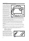
The tool compensations can be selected and/or modified from the operator's panel on OFFSET
screen and from the program with the use of instruction G10. If the current compensation is modified
with command G10, reference has to be made again to the current compensation register D or H, or
else the modified value will be disregarded.
The limit values of address H or D for the given control system, i.e., the numbers of length and
radius compensations to be specified in that control system, are determined by the memory
configuration of the control. In the case of a minimum memory configuration, the number of
compensations is 99, i.e., the limit values of addresses H and D are 0 to 99.
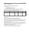
14.2 Modification of Tool Compensation Values from the Program (G10)
Instruction
G10 R L P
can be used for modifying the tool compensations from the program. G10 is a one-shot instruction.
The addresses and their values have the following meanings.
The compensation value is specified at address R. At G90 (absolute data specification command),
the value written at address R will be transferred to the appropriate compensation register. At G91
(incremental data specification command) or when operator I is applied, the data written at address
R will be added to the content of the appropriate compensation register.
The compensation value to be modified is specified at address L:
L=10 applies to the geometry value of the length compensation (code H),
L=11 applies to the wear of the length compensation (code H),
L=12 applies to the geometry value of the radius compensation (code H)
L=13 applies to the wear of the radius compensation (code H),
The No. of compensation value to be modified is specified at address P.
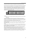
L Note: For a programmed modification of the tool radius compensation, the value specified at
address R must be interpreted as a radius in each case regardless of the state of parameter
TOOLRAD. The control will return error message 3001 VALUE EXCESS X,Y,...F
whenever the specified values exceed the limits contained in the above Table.