


5 The Coordinate Data
40
N3 Y120
N4 Y180
N5 Y240
N6 Y300
N7 Y360
N8 G15 G0 X100
5.3 Inch/Metric Conversion (G20, G21)
With the appropriate G code programmed, the input data can be specified in metric or inch units.
G20: Inch input programming
G21: Metric input programming
At the beginning of the program, the desired input unit has to be selected by specifying the
appropriate code. The selected unit will be effective until a command of opposite meaning is issued,
i.e., G20 and G21 are modal codes. Their effect will be preserved even after power-off, i.e., the unit
prevailing at the time of power-off will be effective after power-on.
The change of the unit will affect the following items:
– Coordinate and compensation data,
– Feed,
– Constant surface speed
– Position, compensation and feed displays.
5.4 Specification and Value Range of Coordinate Data
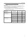
Coordinate data can be specified in 8 decimal digits.
The decimal point will be interpreted as the function of the unit of measure applied:
– X2.134 means 2.134 mm or 2.134 inch,
– B24.36 means 24.36 degrees when address B refers to a rotary axis.
The use of a decimal point is not mandatory.
– X325 means e.g. 325 mm.
The leading zeros may be omitted.
– .032=0.032
The trailing zeros may be omitted behind the decimal point.
– 0.320=.32
The control will interpret a number with more decimals defined by the increment system. For
example, command X1.23456 will be, when IS-B increment system is selected, interpreted as
– 1.235 mm (metric unit),
– 1.2346 inch (inch unit).
Accordingly, the input data will be output as rounded values.