


4.6 Polar Coordinate Interpolation (G12.1, G13.1)
32
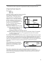
Programming length coordinates in the course of polar coordinate interpolation
In the switched-on state of the polar coordinate interpolation length coordinate data may be
programmed on both axes belonging to the selected plane; The rotary axis in the selected plane
functions as the second (virtual) axis. If e.g. axes X and C have been selected by means of
command G17 X_ C_ address C can be programmed like axis Y in the case of plane selection G17
X_ Y_.
The programming of the first axis being in diameter does not influence the programming of the
virtual axis, the coordinate data must always be given in radius for the virtual axis. If, e.g., polar
coordinate interpolation is executed in plane X C the value written at address C must be specified in
radius, independent of address X given in diameter or radius.
Move of axes not taking part in polat coordinate interpolation
The tool on these axes moves normally, independent of the switched-on state of the polar
coordinate interpolation.
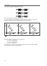
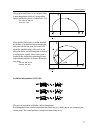
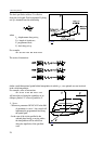
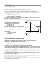
Programming circular interpolation in the course of polar coordinate interpolation
Definition of a circle in polar coordinate interpolation mode is possible as known by means of the
radius or by programming the circle center coordinates. In the latter case addresses I, J, K must be
used according to the selected plane as seen below:
G17 X_ C_
G12.1
...
G2 (G3) X_ C_ I_ J_
G18 Z_ B_
G12.1
...
G2 (G3) B_ Z_ I_ K_
G19 Y_ A_
G12.1
...
G2 (G3) Y_ A_ J_ K_
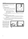
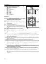
Use of tool radius compensation in case of polar coordinate interpolation
Commands G41, G42 can be used customary in polar coordinate interpolation. The following
restrictions must be considered regarding its application:
– Switch-on of polar coordinate interpolation (command G12.1) is only possible in state G40,
– If G41 or G42 is switched on in state G12.1, G40 must be programmed before switching polar
coordinate interpolation off (command G13.1).
Programming restrictions in the course of polar coordinate interpolation
The below commands cannot be used in the switched-on state of polar coordinate interpolation:
– plane change: G17, G18, G19,
– coordinate transformations: G52, G92,
– work coordinate system change: G54, ..., G59,
– orientation in machine coordinate system: G53.
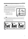
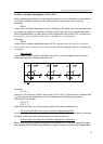
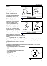
Feed in the course of polar coordinate interpolation
Interpretation of feed in polar coordinate interpolation is tangential speed as in case of right angle
interpolation: The relative speed of piece and tool is defined.
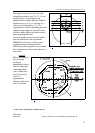
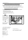
With polar coordinate interpolation the path described in a Cartesian coordinate system is done by
moving a linear and a rotary axis. As the tool center approaches the circular axis of rotation, the
rotary axis should have to take larger and larger steps within a time unit so that the path speed is
constant. However the maximum speed permitted for the rotary axis defined by parameter limits
circular axis speed. Therefore, near to the origin the control decreases feed step by step for the
rotary axis speed not to exceed all limits.