


4.6 Polar Coordinate Interpolation (G12.1, G13.1)
33
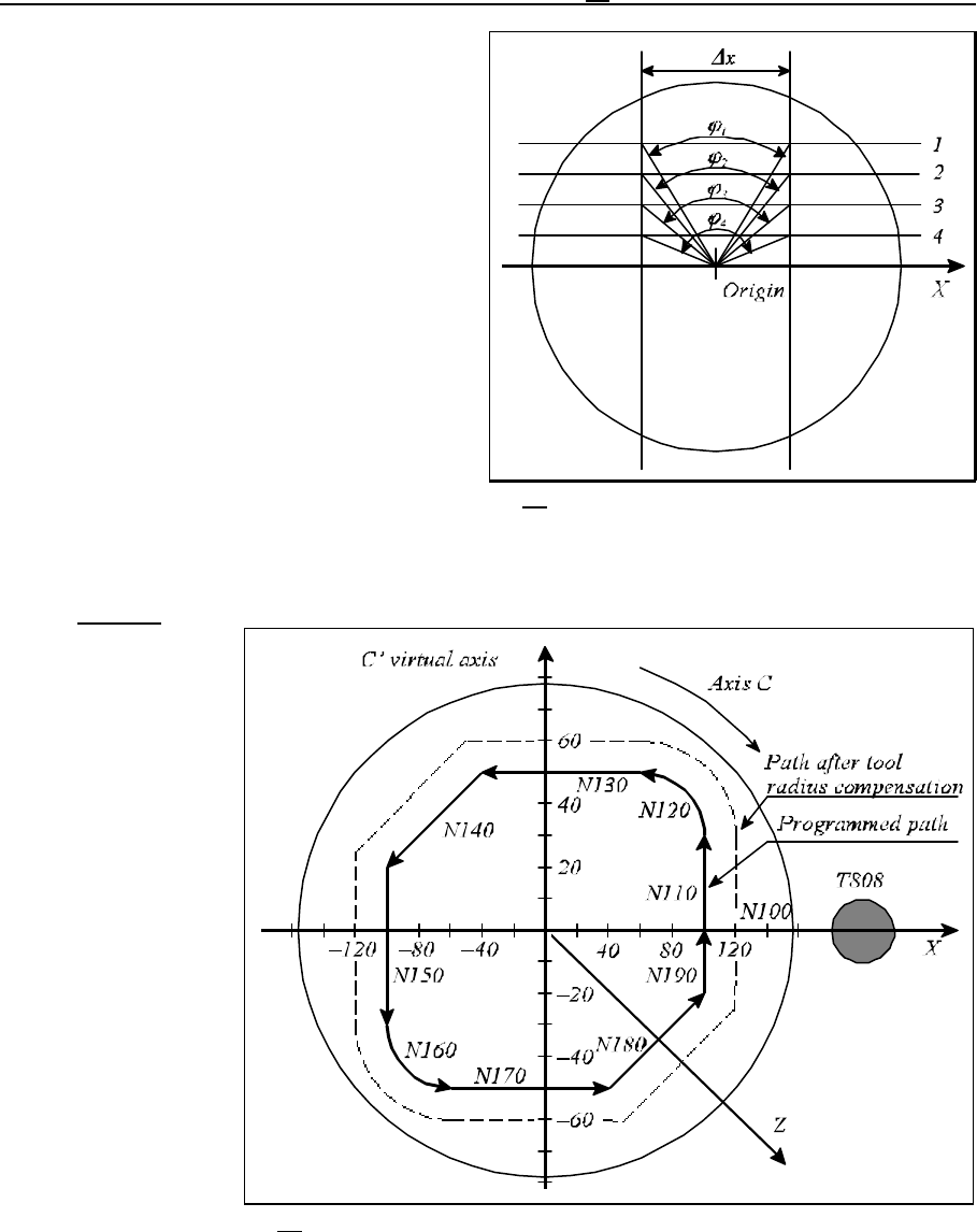
Fig. 4.6-2
Fig. 4.6-3
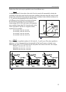
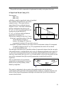
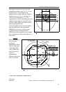
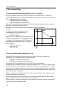
The diagram beside shows the cases when
straight lines parallel to axis X (1, 2, 3, 4) are
programmed. )x move belongs to the
programmed feed within a time unit. Different
angular moves (n
1
, n
2
, n
3
, n
4
) belong to )x
move for each straight lines (1, 2, 3, 4).
Apparently, the closer the machining gets to the
origin the larger angular movement the rotary
axis has to make within a time unit in order to
keep the programmed feed.
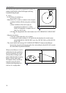
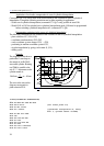
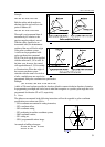
In case the angular move to be made within a
time unit exceeds the value of parameter
FEEDMAX set for rotary axis the control
gradually decreases the tangential feed.
With these in mind, programs in case of which
the tool center moves close to the origin are to
be avoided.
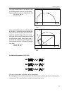
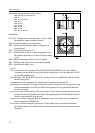
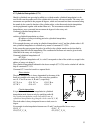
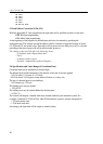
Example
Below an example for
the use of polar
coordinate
interpolation is shown.
The axes taking part
in the interpolation:
Axes X (linear axis)
and C (rotary axis).
Axis X is
programmed in
diameter, while that of
axis C is in radius.
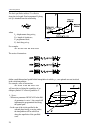
%O7500(POLAR COORDINATE INTERPOLATION)
...
N050 T808
N060 G59 (start position of coordinate system G59 in