


5 The Coordinate Data
39
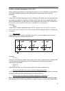
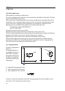
Fig. 5.2-1
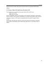
Fig. 5.2-2
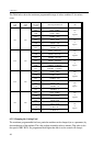
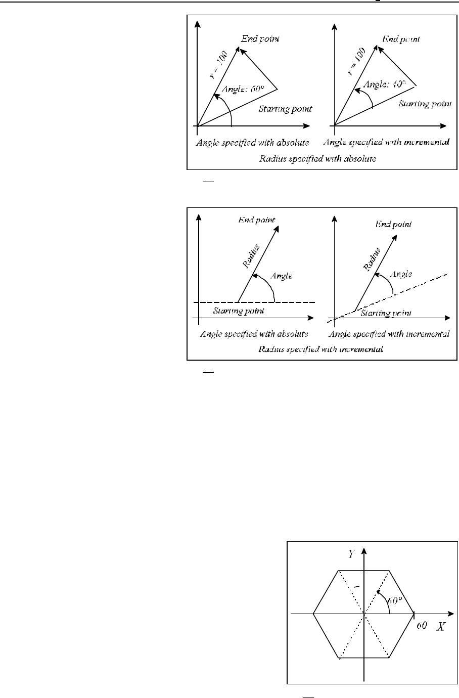
Fig. 5.2-3
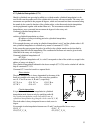
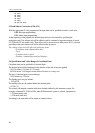
Example:
G90 G16 G01 X100 Y60 F180
Both the radius and the angle are
absolute data, the tool moves to the
point of 100mm; 60°.
G90 G16 G01 X100 YI40 F180
The angle is an incremental data. A
movement by 40° relative to the
previous angular position is moved.
With the radius, specified as an
incremental value, the instantaneous
position of the axes will be the origin
of the polar coordinate system.
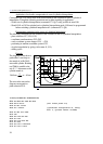
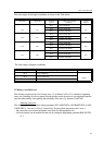
A circle can be programmed with
polar coordinate data command
(G16). The circle can be also specified
with the radius and I, J, K as well. In
the latter case, however, the control
will regard addresses I, J, K invariably
as Cartesian data. When the origin of
the current coordinate system
coincides with the center of a circle or
a helix, a multiple turn one can also be
programmed with polar coordinate data specification.
Example:
(G17 G16 G90) G02 X100 Y-990 Z50 R-100
A helix of 2¾ turns has been specified in the above block in counter-clockwise direction of rotation.
In programming a multiple-turn circle, bear in mind that a negative or a positive polar angle has to be
programmed for direction G2 or G3, respectively.
L Notes:
The addresses encountered in the following instructions will not be regarded as polar coordinate
specifications even when state G16 is:
– G10 coordinates encountered in setting instruction,
– G52 coordinate offset,
– G92 coordinate setting,
– G53 positioning in machine coordinate system,
– G68 coordinate rotation,
– G51 scaling on,
– G50.1 programmable mirror image.
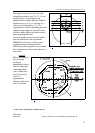
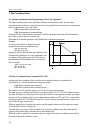
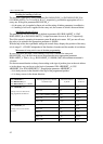
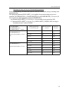
An example of milling a hexagon:
N1 G90 G17 G0 X60 Y0 F120
N2 G16 G1 Y60