


17 Canned Cycles for Drilling
154
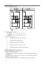
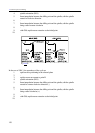
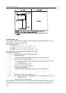
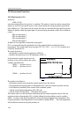
Fig. 17.1.12-2
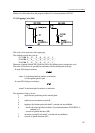
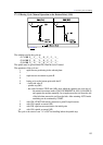
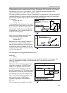
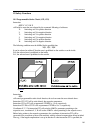
B. Back Boring Cycle
If the machine is provided with the facility of spindle orientation (parameter ORIENT1=1), the
control will act in conformity with case "B".
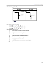
The variables of cycle are
G17 G87 X
p
__ Y
p
__ I__ J__ Z
p
__ R__ F__ L__
G18 G87 Z
p
__ X
p
__ K__ I__ Y
p
__ R__ F__ L__
G19 G87 Y
p
__ Z
p
__ J__ K__ X
p
__ R__ F__ L__
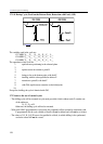
The spindle must be given rotation M3 when the cycle is started.
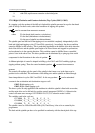
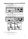
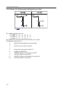
The operations of cycle are
1.
rapid-traverse positioning in the selected plane
2.
– spindle orientation
– tool receded in the selected plane with values I, J, K (rapid traverse)
3.
rapid-traverse movement to point R
4.
– tool receded in the selected plane opposite to the values specified at I, J or K
(rapid traverse)
– spindle re-started in direction M3
5.
boring as far as the point Z, with feed F
6.
– spindle orientation (M19)
– tool receded in the selected plane with values I, J, K (rapid traverse)
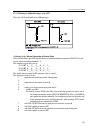
7.
-
8.
-
9.
rapid-traverse retraction to the initial point
10.
– tool receded in the selected plane opposite to the values specified at I, J or K
(rapid traverse)
– spindle re-started in direction M3
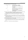
Following from the nature of the cycle, point R is located, unlike in the previous instances, lower
than point Z. This must be taken into account in programming the boring axis and addresses R.