


2-4 Preliminary May 9, 2000 APX 8000/MAX TNT/DSLTNT Physical Interface Configuration Guide
Configuring Shelf-Controller Redundancy (APX 8000)
Configuring the APX 8000 for shelf-controller redundancy
Assigning the system IP address
To configure an APX 8000 that has redundant shelf controllers, you must map system IP
settings to the unit’s soft IP interface. The soft IP interface is associated with the shelf
controller that is currently primary.
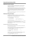
Set the IP-Global profile’s System-IP-Addr parameter to the address of the soft IP interface.
System-IP-Addr must not be set to a particular physical interface, such as the address of a shelf
controllers. In a redundant shelf-controller system, the physical address of the primary
controller changes according to which controller is currently primary, and the system IP
address must be a single, unchanging address that always maps to the current primary
controller.
Configuration of the soft IP interface address is described in the section “Defining the soft IP
interface for fault tolerance” on page 2-5.
Assigning an Ethernet IP address
An APX 8000 creates an IP interface for the Ethernet port of each shelf controller. The
IP-Interface profile index is based on each controller’s slot number. The left controller slot on
the TAOS unit is number 41, and the right controller slot is 42.
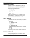
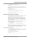
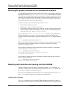
To list the IP interfaces, use the Dir command, as follows:
admin> dir ip-interface
6 06/17/1999 03:06:00 { { any-shelf any-slot 0 } 0 }
19 06/21/1999 23:54:02 { { shelf-1 left-controller 1}0}
19 06/25/1999 17:45:30 { { shelf-1 right-controller1}0}
The IP interface profile indicated by {{ shelf-1 left-controller 1 } 0} is for the
shelf controller in the first controller slot. The IP profile indicated by {{ shelf-1
right-controller 1 } 0} is for the shelf controller in the second controller slot. The
IP-Interface profile with the zero index {{ any-shelf any-slot 0 } 0} is reserved
for the soft IP interface.
Examples of setting shelf-controller Ethernet IP address
Each shelf controller needs to be assigned an IP address. Following are examples that show
how to configure the Ethernet IP addresses.
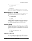
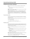
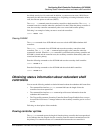
In the following example, the shelf controller in the left controller slot position (slot 41) is the
primary controller. The primary controller is assigned the address 192.168.100.1/24:
admin> read ip-interface { { 1 41 1 } 0 }
IP-INTERFACE/{ { shelf-1 left-controller 1 } 0 } read
admin> set ip-address = 192.168.100.1/24
admin> write
IP-INTERFACE/{ { shelf-1 left-controller 1 } 0 } written
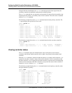
The following commands assign the address 192.168.100.2/24 to the secondary (right) shelf
controller. The commands must be performed on the primary (left) controller.
admin> read ip-interface { { 1 42 1 } 0 }
IP-INTERFACE/{ { shelf-1 right-controller 1 } 0 } read