


9-12 Preliminary May 9, 2000 APX 8000/MAX TNT/DSLTNT Physical Interface Configuration Guide
Configuring E1 Cards
Configuring DPNSS signaling
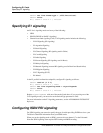
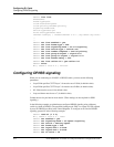
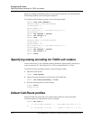
admin> list line
enabled=no
frame-type=g703
clock-source=eligible
clock-priority=middle-priority
signaling-mode=isdn
switch-type=net5-pri
front-end-type=short-haul
channel-config=[ { unused-channel 9 "" { any-shelf any-slot+
..
..
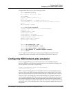
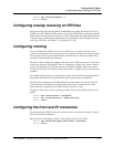
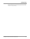
admin> set line enabled = yes
admin> set line frame-type = 2DS
admin> set line signaling-mode = e1-r2-signaling
admin> set line switch-type = switch-cas
admin> set line number-complete = end-of-pulsing
admin> set line group-b-signal = signal-b-6
admin> set line group-ii-signal = signal-ii-2
admin> set line answer-delay = 200
admin> set line caller-id = get-caller-id
admin> write
E1/{ shelf-1 slot-2 2 } written
Configuring DPNSS signaling
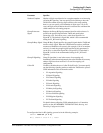
When you are connecting to a DASS 2 or DPNSS switch, you must set the following
parameters:
• Layer3-End specifies CCITT Layer 3. It must be set to X-Side (its default value).
• Layer2-End specifies CCITT Layer 2. It must be set to B-Side (its default value).
• NL-Value must be set to 64 (its default value).
• Loop-avoidance must be set to 7 (its default value).
Contact the service provider for more details. (These settings are not required for ISDN
signaling.)
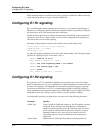
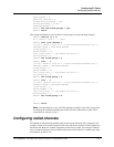
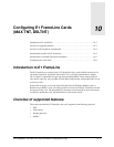
In the following example, an administrator configures DPNSS signaling using a Mercury
switch (a variant of DPNSS). The specified framing mode, 2DS, is a variant of G.703 required
by most E1 DPNSS providers in the United Kingdom. To configure an E1 line for DPNSS
signaling, proceed as in the following example:
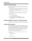
admin> read e1 {1 2 2}
E1/{ shelf-1 slot-2 2 } read
admin> set enabled = yes
admin> set signaling-mode = e1-dpnss-signaling
admin> set switch = mercury-dpnss
admin> set frame-type = 2ds
admin> set layer3-end = x-side
admin> set layer2-end = b-side
admin> set nl-value = 64