


9-10 Preliminary May 9, 2000 APX 8000/MAX TNT/DSLTNT Physical Interface Configuration Guide
Configuring E1 Cards
Configuring E1 R1 signaling
ISDN emulation enables you to build, send, receive, and process ISDN data. ISDN monitoring,
on the other hand, allows you only to decode the ISDN data.
Configuring E1 R1 signaling
R1 is a multifrequency inband signaling protocol that uses a set of register signals known as
MFR1 tones as addressing signals. Each address (telephone number) is preceded by a KP pulse
and followed by an ST pulse denoting the end of addressing.
The R2 signaling option must be software licensed (hash-code enabled) on the system for R1
signaling to work. If one or more E1 lines on an E1 card are configured for R1 signaling, no
other line on the card can use R2 signaling.
Following are the parameters relevant to R1 signaling, shown with sample values:
[in E1/{shelf-1 slot-13 1}:line-interface]
signaling-mode = r1-inband
switch-type = cas
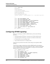
All other line signaling parameters can be left in their default settings. The following example
specifies R1 signaling on an E1 line in shelf 1, slot 13:
admin> read e1 {1 13 1}
E1/{ shelf-1 slot-13 1 } read
admin> set line signaling-mode = r1-inband
admin> set switch-type = cas
admin> write
E1/{ shelf-1 slot-13 1 } written
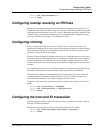
Configuring E1 R2 signaling
R2 signaling is an ITU-T standardized signaling protocol, which can be used on E1 digital
trunks for switched circuits. It uses a combination of A/B bit manipulation in channel 16 of the
E1 frame (line signaling), and inband MF tone generation and detection (register signaling).
The relevant specifications are in ITU-T recommendations Q.400 to Q.490. R2 signaling is
widely implemented in international markets where ISDN PRI is not yet available. The default
bandwidth for data calls coming in over E1 channels using R2 signaling is 64Kbps.
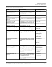
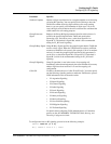
To configure R2 signaling, you might need to set some or all of the following parameters:
Parameter Specifies
Switch-Type Type of switch the TAOS unit connects to. For R2 signaling, you must
set Switch-Type to Switch-CAS. When the line is configured for
channel associated signaling (CAS), the TAOS unit does not receive
bearer-capability information from the carrier. Therefore, it cannot
determine whether a call is voice-service or digital-service. For
call-routing purposes, all calls on inband lines are assumed to be
digital calls.
Answer-Delay Milliseconds the TAOS unit delays before answering an R2 call.