12-2 Preliminary May 9, 2000 APX 8000/MAX TNT/DSLTNT Physical Interface Configuration Guide
Configuring Serial WAN (SWAN) Cards (MAX TNT, DSLTNT)
Understanding SWAN card configuration requirements
For complete information about the associated parameters, see the APX 8000/MAX
TNT/DSLTNT Reference.
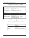
Understanding SWAN card configuration requirements
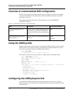
Table 12-2 provides important configuration information you might need before configuring
your SWAN card.
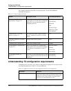
Table 12-1. SWAN-card configuration tasks
Section Description of task Associated parameters
“Understanding SWAN card
configuration requirements” on
page 12-2
Explains important configuration information
you should understand before you configure
the SWAN card.
N/A
“Making a profile the working
profile” on page 12-3
Before you can edit a profile, you must make
it the working profile.
N/A
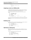
“Assigning a name to a SWAN
profile” on page 12-4
Assign a name to the SWAN profile. Name
“Enabling a line” on page 12-4 Make a line available for use. Enabled
“Specifying a nailed group” on
page 12-4
The nailed group is used to assign a Frame
Relay connection to a SWAN line.
Nailed-Group
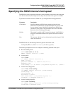
“Specifying the SWAN internal
clock speed” on page 12-5
The SWAN slot card can generate a transmit
internal clock based on the clock speed of its
Serial Communication Adapter (SCA) chips.
Clock-Mode
Divider
Exp
Table 12-2. SWAN card configuration
Element Explanation
Connections The SWAN card currently supports only nailed Frame
Relay connections.
Call routing information Call routing information for the SWAN card is
currently ignored.
Trunk groups Trunk groups are not currently implemented for the
SWAN card.


