17-12 Preliminary May 9, 2000 APX 8000/MAX TNT/DSLTNT Physical Interface Configuration Guide
Configuring DSL Connections (DSLTNT)
Configuring DSLPipe Plug and Play
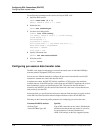
LOG info, Shelf 1, Controller, Time: 16:47:34--
[1/7/1/0] Assigned to port [MBID 19]
LOG info, Shelf 1, Controller, Time: 16:47:34--
[1/7/1/1] Call Connected [MBID 19]
LOG info, Shelf 1, Slot 7, Time: 16:47:39--
[1/7/1/0] LAN session up: <adslpipe-1> [MBID 19]
[adslpipe-1]
LOG notice, Shelf 1, Slot 7, Time: 16:47:39--
Line 1 (radius) profile adslpipe-1
from <autobaud,1088000,2560000>
to <autobaud,952000,7168000>
LOG notice, Shelf 1, Slot 7, Time: 16:47:39--
Line 1 (radius) profile adslpipe-1 successfully retrained
<autobaud,952000,7168000>
Configuring DSLPipe Plug and Play
The Plug and Play feature enables a DSLPipe to obtain its configuration through the DSLTNT
by using the Dynamic Host Configuration Protocol (DHCP) and Trivial File Transfer Protocol
(TFTP). The DSLPipe ships with the Plug and Play feature enabled, so it requires no
configuration if the DSLTNT and servers have been configured properly.
How Plug and Play works
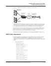
When the DSLPipe unit initially comes up, it uses factory default settings that enable it to
forward a DHCP request to a DSLNT, which sends the request to a DHCP server. The
connection between the DSLTNT and the DSLPipe is a nailed Frame Relay-encapsulated
connection configured for bridging.
The DHCP server returns an IP address, netmask, the path to a more detailed configuration
file, and a TFTP server hostname. The DSLTNT forwards the DHCP response to the requesting
DHCP client.
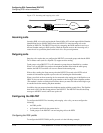
Figure 17-1 illustrates the Plug and Play feature.


