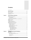
Contents
APX 8000/MAX TNT/DSLTNT Physical Interface Configuration Guide xi
Sample Frame Relay IDSL configuration .................................................................. 17-22
Configuring the DSLTNT ................................................................................... 17-23
Configuring the Pipeline...................................................................................... 17-25
Sample ADSL nailed PPP connection........................................................................ 17-26
Configuring the ADSL profile............................................................................. 17-27
Configuring the Connection profile..................................................................... 17-27
Configuring the DSLPipe.................................................................................... 17-28
Sample SDSL Frame Relay configuration using numbered interfaces ...................... 17-29
Configuring the Connection profile..................................................................... 17-30
Configuring the IP-Route profile......................................................................... 17-31
Configuring the SDSL profile ............................................................................. 17-32
Configuring the Frame-Relay profile .................................................................. 17-32
Configuring the DSLPipe-S................................................................................. 17-33
Sample SDSL Frame Relay configuration using system-based routing..................... 17-34
Configuring the Connection profile..................................................................... 17-34
Configuring the SDSL profile ............................................................................. 17-36
Configuring the Frame-Relay profile .................................................................. 17-36
Configuring the DSLPipe-S................................................................................. 17-36
Chapter 18 Signaling System 7 (SS7)............................................................. 18-1
Introduction to SS7.............................................................................................................. 18-1
System requirements for SS7 operations ............................................................................. 18-2
TAOS unit as terminator of data calls in an SS7 network............................................ 18-2
TAOS unit as terminator of voice and data calls in an SS7 network............................ 18-3
Interface between a signaling gateway and TAOS unit................................................ 18-4
Incoming calls............................................................................................................... 18-4
Continuity tests ............................................................................................................. 18-4
Configuring an SS7 signaling gateway................................................................................ 18-4
Specifying the SS7 control protocol............................................................................. 18-6
Configuring transport-layer options.............................................................................. 18-6
System IP address considerations................................................................................. 18-7
Example of a basic configuration ................................................................................. 18-8
T1 lines as SS7 data trunks........................................................................................... 18-8
Example of configuring a T3 card for SS7 data.................................................... 18-9
Example of configuring a T1 data trunk................................................................ 18-9
E1 lines as SS7 data trunks......................................................................................... 18-10
V.110 bearer capability for SS7 calls using IPDC...................................................... 18-11
SS7 link establishment timer ...................................................................................... 18-11
Two-wire continuity check on T1 and E1 lines.......................................................... 18-11
Outgoing continuity tests on T1 and T3 ..................................................................... 18-13
Digital milliwatt tone support on T1 and T3 .............................................................. 18-13
Analog milliwatt tone and variable tone support........................................................ 18-13
Reporting VoIP call statistics ..................................................................................... 18-14
When the unit reports VoIP statistics .................................................................. 18-14
ss7nmi debug-level command ............................................................................. 18-15
Statistics and error reporting on SS7 connections ...................................................... 18-15
Command output when no errors are detected .................................................... 18-15
Command output showing errors ........................................................................ 18-18
Cause codes for SS7 ASGCP calls to the TAOS unit........................................................ 18-19
SS7 IPDC support for call ID and disconnect cause codes ........................................ 18-20
IPDC generation of a globally unique call ID ..................................................... 18-20
Global-Call-ID parameter.................................................................................... 18-20


