


C-27
REGISTERS
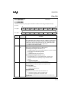
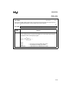
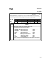
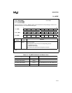
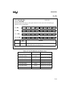
INT_PEND
INT_PEND
Address:
Reset State:
0009H
00H
When hardware detects an interrupt request, it sets the corresponding bit in the interrupt pending
(INT_PEND or INT_PEND1) registers. When the vector is taken, the hardware clears the pending bit.
Software can generate an interrupt by setting the corresponding interrupt pending bit.
7 0
MC, MD COMP2 EPA2
COMP1 EPA1 COMP0 EPA0 AD OVRTM
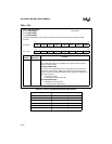
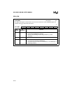
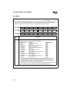
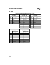
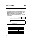
7 0
MH COMP3 COMP2
COMP1 EPA1 COMP0 EPA0 AD OVRTM
Bit
Number
Function
7:0 Any set bit indicates that the corresponding interrupt is pending. The interrupt bit is cleared
when processing transfers to the corresponding interrupt vector.
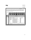
The standard interrupt vector locations are as follows:
Bit Mnemonic Interrupt Standard Vector
COMP2 (MC, MD) EPA Compare Channel 2 200EH
COMP3 (MH) EPA Compare Channel 3 200EH
EPA2 (MC, MD) EPA Capture/Compare Channel 2 200CH
COMP2 (MH) EPA Compare Channel 2 200EH
COMP1 EPA Compare Channel 1 200AH
EPA1 EPA Capture/Compare Channel 1 2008H
COMP0 EPA Compare Channel 0 2006H
EPA0 EPA Capture/Compare Channel 0 2004H
AD A/D Conversion Complete 2002H
OVRTM
†
Overflow/Underflow Timer 2000H
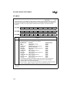
†
Timer 1 and timer 2 can generate the multiplexed overflow/underflow interrupt. Write to
PI_MASK to enable the interrupt sources; read PI_PEND to determine which source
caused the interrupt.