8XC196MC, MD, MH USER’S MANUAL
9-12
9.4 PROGRAMMING THE WAVEFORM GENERATOR
This section explains how to configure the waveform generator and determine its status.
9.4.1 Configuring the Outputs
The waveform generator’s outputs are multiplexed with general-purpose output port 6, so you
must configure them as special-function signals to use them as waveform-generator outputs. The
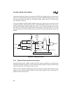
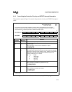
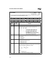
WG_OUTPUT register (Figure 9-8) configures the pins, establishes the output polarity, and con-
trols whether changes to the outputs are synchronized with an event or take effect immediately.
Four bits of WG_OUTPUT are unrelated to the waveform generator; they configure the outputs
for the pulse-width modulator (PWM) peripheral, which also shares pins with port 6. The P6 and
PE6 bits control the P6.6/PWM0 pin, and the P7 and PE7 bits control the P6.7/PWM1 pin. Their
placement in this register allows you to configure all the port 6 pins with a single write to
WG_OUTPUT.
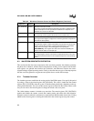
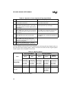
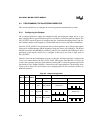
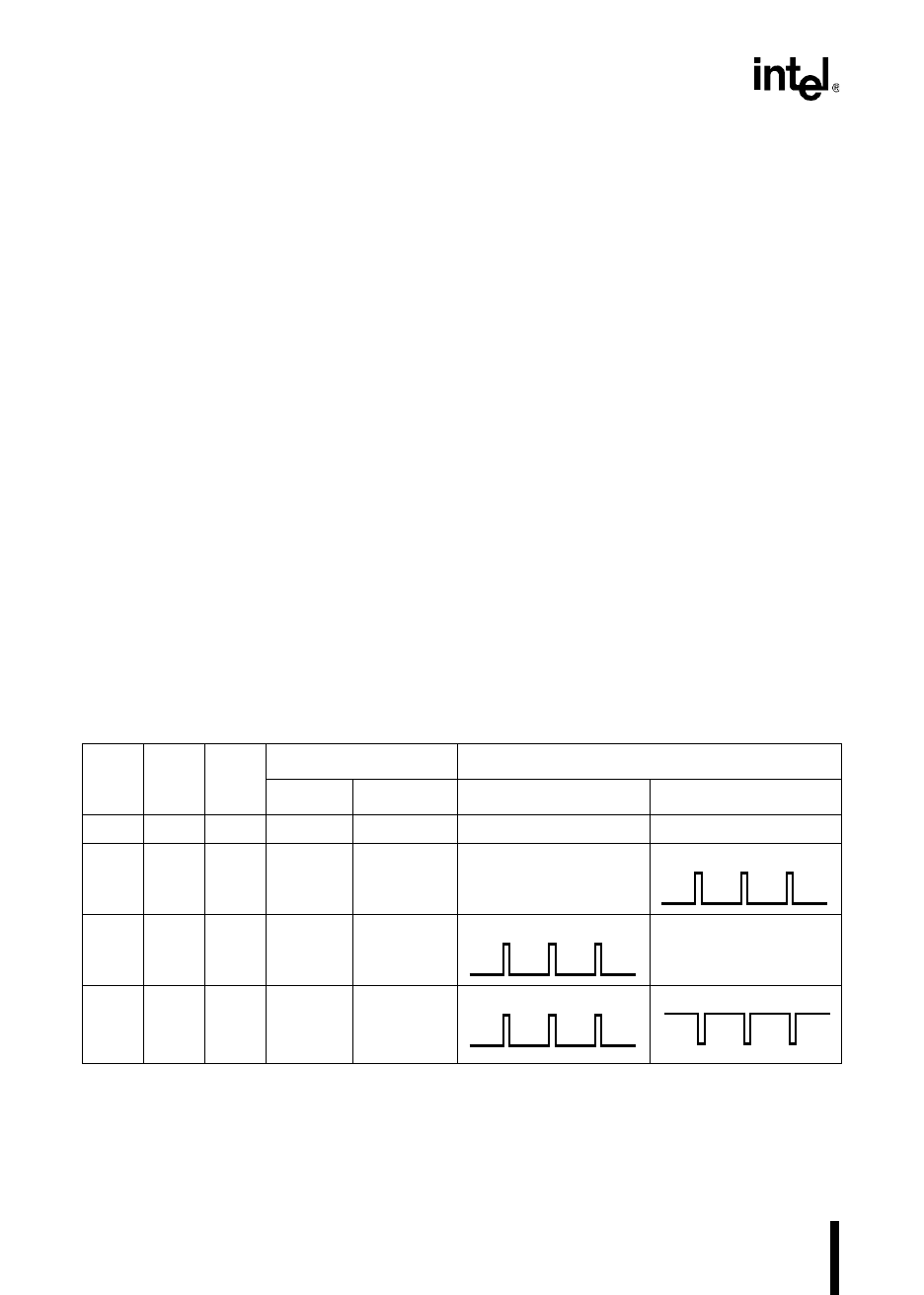
Table 9-5 shows the bit combinations necessary to drive the waveform generator’s outputs high
or low or to connect them to the WG_EVEN or WG_ODD signal. Note that PHx.2 is always set
to select the waveform-generator signal function (clearing PHx.2 selects the general-purpose I/O
port function). The “Output Polarities” column shows the output polarities. The drawings show
a duty cycle of about 15%, and for these cases, the high portion of the waveforms increases as
dead time increases.
,
Table 9-5. Output Configuration
PH
x
.2 PH
x
.1 PH
x
.0
Output Values Output Polarities
WG
x
WG
x
#WG
x
WG
x
#
1 0 0 Low Low Always Low Always Low
1 0 1 Low WG_EVEN# Always Low
1 1 0 WG_ODD Low Always Low
1 1 1 WG_ODD WG_EVEN
NOTE: This table assumes active-high outputs (OP1=OP0=1).


